34
Mod. ITACA-TROIA rev 01
Installation
translated from the original text
IT IT
FR
FR
ES ES
EN EN
Ref. Description
1
Radiator H2O supply ¾”
2
H2O exhaust pipe safety valve ½”
3
Radiator H2O return ¾”
2.5.6 FLUE GAS EXHAUST DUCT
The exhaust pipe must be constructed by special-
ised, skilled personnel or companies, according to
the indications in this manual. The exhaust system
must be made in such a way as to ensure easy peri-
odic cleaning without having to disassemble any
parts.
The pipes must ALWAYS be installed according to the standards
and instructions of the manufacturer and anyway with the silicon
gasket supplied to guarantee its sealing.
• IT is prohibited to install dampers or other valves that can
obstruct the ue gas exhaust.
• IT is prohibited to install one ue in which ue gas or vapours of
other appliances (boilers, hoods, etc.) are exhausted.
2.5.7 PIPES AND MAXIMUM USABLE LENGTHS
Pipes made of painted aluminised steel (minimum thickness
1.5 mm), stainless steel (Aisi 316) with a 100 mm diameter (for
pipes inside the ue max. 150 mm). Hoses are prohibited; the
male-female coupling collars must have a minimum length
of 50 mm. The diameter of the pipes depends on the type of
system.
TYPE OF SYSTEM
WITH Ø 100 mm DOU-
BLE WALLED PIPE
Minimum length 2m
Maximum length (with 3 90° elbows) 8m
For installations located at over 1200 m asl mandatory
Maximum number of elbows 4
Horizontal segments with min slope 5% 2m
tab.3 max. pipe length
NOTE: pressure drops of a 90° elbow can be com-
pared to those of a 1 metre pipe; the inspection
tee tting must be considered as a 90° elbow. Re-
fer to the standards in force in question.
Tee tting
Ref. Description
1 Radiator supply
2 Radiator return
3 Water mains
g. 8 water mains connection diagram
Water mains connection must be carried out by
qualied personnel in order to prevent malfunc-
tions or faults to the boiler itself. For proper circu-
lation of water, it is advised to reduce the diameter of the
supply and return pipes.
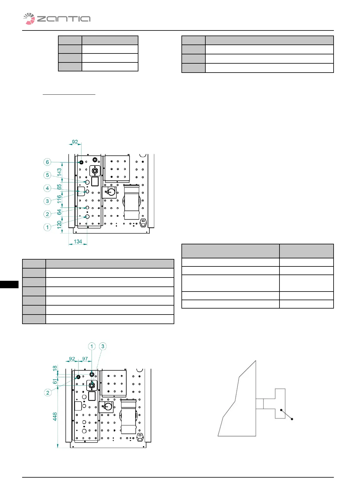
DHW kit connection:
g. 9 connection points with the DHW kit
Ref. Description
1
Radiator H2O supply ¾”
2
DHW output ½”
3
H2O cold hydraulic line input ½”
4
Charge tap
5
H2O return hot radiators ¾”
6
H2O exhaust pipe safety valve ½”
Connection without the DHW kit
g. 10 connection points without a DHW kit