39
Mod. ITACA-TROIA rev 01
Instructions for use
translated from the original text
IT IT
FR
FR
ES ES
EN EN
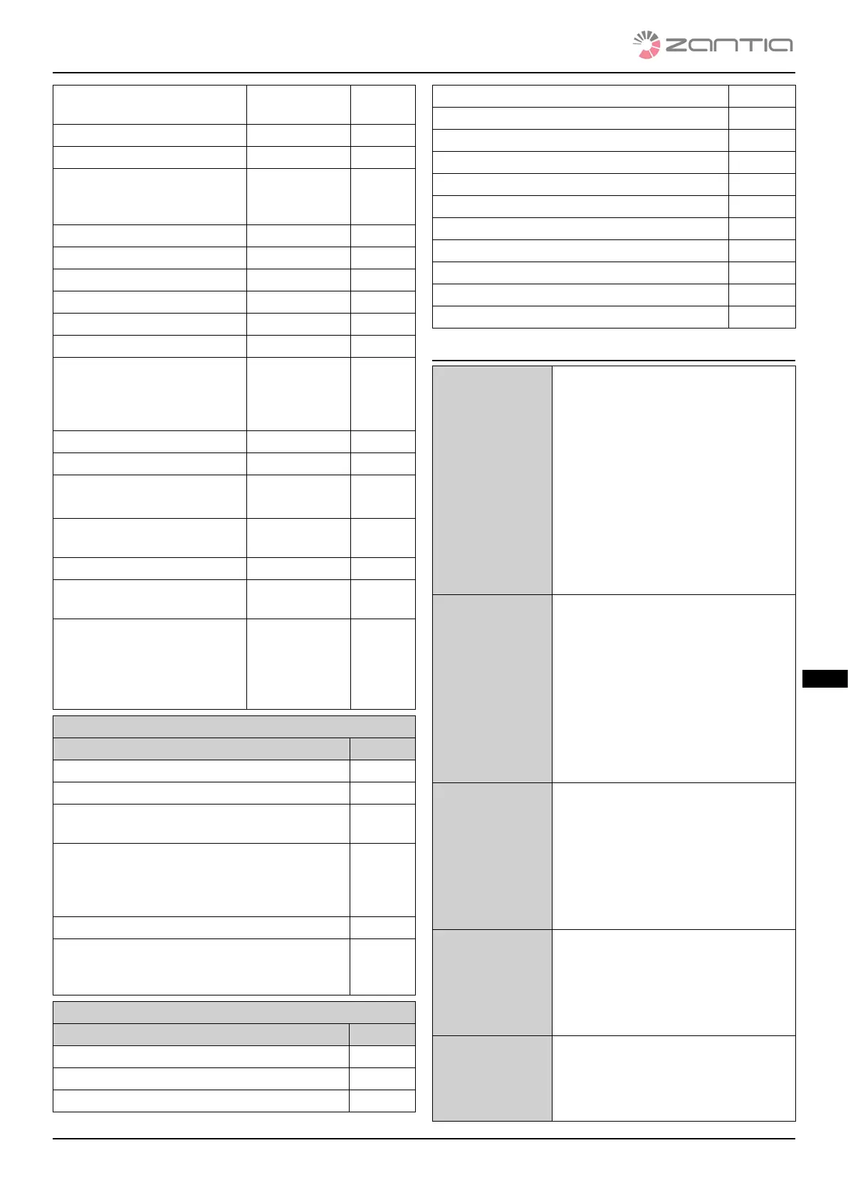
Encoder error: combustion fan
speed adjustment failure
Block status Er08
Low water pressure Block status Er09
High water pressure Block status Er10
Incorrect date/time values
after prolonged absence of
mains power supply
Block status Er11
Ignition failure Block status Er12
Voltage gap Block status Er15
Air ow regulation failed Block status Er17
No fuel Block status Er18
Brazier cleaning motor error Block status Er25
Flow switch sensor broken Block status Er39
Minimum air ow not reached
during check-up/‘poor
draught’ test failure during
check-up
Block status Er41
Maximum air ow exceeded Block status Er42
Door error Block status Er44
Auger encoder error:
no encoder signal
Block status Er47
Auger encoder error: failed
auger speed adjustment
Block status Er48
I/O i2c modules error Block status Er52
‘Excessive draught’ test failure
during check-up
Block status Er57
Service error. Indicates that
the programmed operating
hours have been reached.
You are required to call the
Assistance Service.
Block status Seru
Messages
Description Code
Probe control fault during check-up phase Sond
Water temperature inside the boiler above 99°C Hi
Indicates that the programmed operating hours
have been reached.
Clr
Message that appears if the system is switched
o in a non-manual manner during the Switch-
on phase (after pre-loading): the system will only
switch o once operation is steady.
O del
Periodic cleaning in progress Pclr
The message is displayed when DHW is reque-
sted (closed ow switch contact) since a ow
switch is used.
Flu
Display of operating statuses
Status Code
O status -
Check Up status Chec
Ignition - preheating phase On 1
Ignition - pre-loading phase On 2
Ignition - xed phase On 3
Ignition - variable phase On 4
Stabilisation status On 5
Normal status -
Modulation status Mod
Standby Stby
Safety Saf
Switch-O status O
Block status Alt
Restart status Rec
4.2 USER 1 MENU
Displays • Tp: puer temperature [°c]
• Ta: basic room temperature [°c]
• Tf: smoke temperature [°c]
• Uf: combustion fan speed/volta-
ge [rpm/volt]
• Co: auger ON time [rpm/sec]
• Pa: water pressure [mbar]
• Fc: rmware code and revision:
fysyi01000034.X.Y
• 510: Manufacturer’s product
code: 0y.0X
Operating po-
wer adjustment
Simply click k2 or k6: the d2
display ashes. It is possible to
change the power from the values
available by clicking several ti-
mes. E.g.: 1–2–3–4–5–A
(A= automatic combustion)
Aer 3 seconds, the value is saved
and the display goes back to
normal.
Pellet manual
loading
e bottom display shows load,
whereas the top one shows the
loading time elapsed. To stop lo-
ading, press any button. Loading
is Automatically stopped aer
300 seconds. is function is only
available in an O status
Pellet feeding
correction
Enables you to change the default
settings of the speed or ON times
of the Auger. e set values are
between –7÷7. e default setting
is 0.
Combustion
fan correction
Enables you to change the default
settings of the Combustion fan
speed. e set values are between
–7÷7. e default setting is 0.