Solo documento principale.
Identification: MD-AL-GI-00
Rev. 1.2 07.06.21 - Application: GID
Connext User Manual
Rev. 2.2 10/01/2023
The system has a 24-pin terminal block at the bottom for connecting the devices and accessories, a
3-pin terminal block at the top right for power supply connections, an Ethernet connector at the top,
a slot for a microSD card at the top (for possible data storage), a front graphic display and a front
connection for the 4G (or Ethernet) communication antenna.
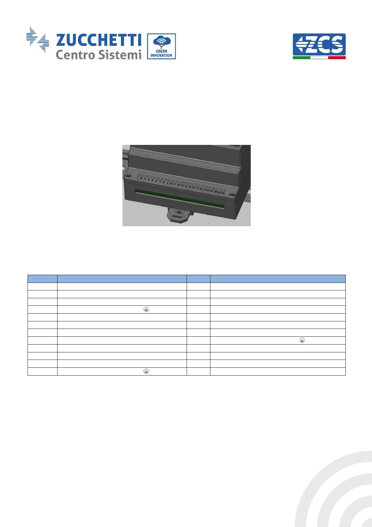
24-pin terminal block
Figure 6 - 24-pin terminal block
The 24-pin terminal block has the following pin-out.
Relay1 normally closed contact
Relay1 normally open contact
Relay2 normally closed contact
Relay2 normally open contact
Table 2 – 24-pin terminal block pin-out
The maximum acceptable cable cross-section for the terminals is 1mm
2
.