Page 18
TO GET ASSISTANCE, CALL: 919-774-7667
ZENITH PUMPS
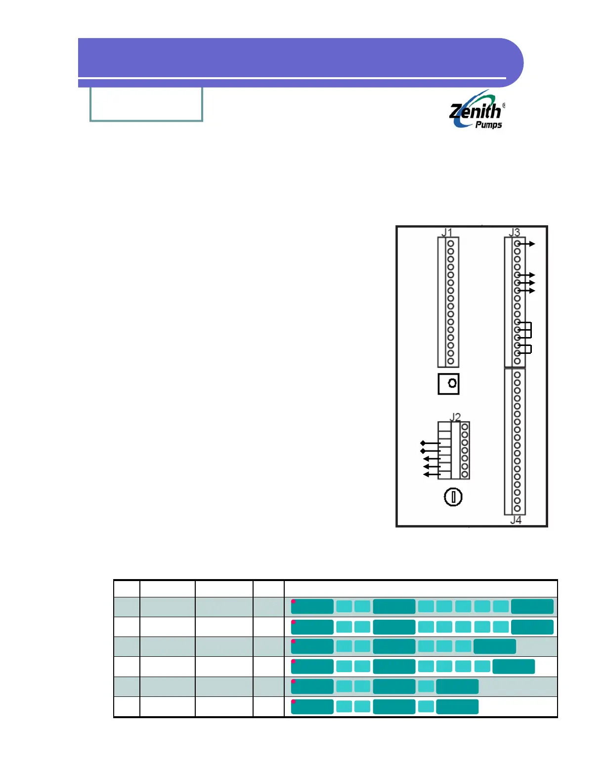
1. Prepare the ZeDrive:
• Place jumpers on J3 connector between
Pin 11 - Pin 12
Pin 13 - Pin 12
Pin 14 - Pin 15
• Connect power wires to J2 connector Pin L1, Neutral and
Chassis GND (Do NOT turn on power at this time)
2. Prepare the Sensor:
• Screw the sensor into the thread hole located on the
gear reducer, until it hits the inside pickup gear, and
back up about 1/8 of a turn (45 degrees)
• If it is a 2-wire sensor, connect
White wire - J3 Pin 5
Black wire - J3 Pin 6
Bare wire - J3 Pin 7
• If it is a 3-wire sensor, connect
Red wire - J3 Pin 1
White wire - J3 Pin 5
Black wire - J3 Pin 6
Bare wire - J3 Pin 7
3. Connect Power to the Drive:
• Turn the 120 VAC power on for the ZeDrive
• If the power is 230 VAC, please refer to “Trouble-
shooting” section
4. Configure ZeDrive:
A 5.091:1 reducer and 120 teeth pickup gear is used for the following example.
Change values for codes 20, 22 and 31 based on the system.
Quick Test for ZeDrive
1
2
3
4
5
6
7
8
9
10
11
12
13
14
15
16
Red
Wht
Bare
Blk
To
Feedback
Sensor
Jumpers
To Motor
To AC
Power
A2
A1
L1
N
G
Back Panel of ZeDrive
Code Description Formula
20 Primary Setpoint
Eng. Unit
1800/Gear Ratio
(i.e., 5.091:1)
Default
353.6
Operation
22 Primary Display
Eng. Unit
1800/Gear Ratio
(i.e., 5.091:1)
353.6
31 No. of Teeth of
Feedback Gear
120 120
34 Primary RPM Max
Feedback
1800 1800
61 Primary Scaling
Format
1 1
63 Primary Display
Format
1 1
CODE
SELECT
2 0
ENTER
3 5 3
.
6
ENTER
CODE
SELECT
2 2
ENTER
3 5 3
.
6
ENTER
CODE
SELECT
3 1
ENTER
1 2 0
ENTER
CODE
SELECT
3 4
ENTER
1 8 0 0
ENTER
CODE
SELECT
6 1
ENTER
1
ENTER
CODE
SELECT
6 3
ENTER
1
ENTER