Page 27
TO GET ASSISTANCE, CALL: 919-774-7667
ZENITH PUMPS
Feedback Control by Using a Flowmeter with Frequency Signal
1. Preliminary Action:
• A flowmeter which can send frequency flow signal to ZeDrive
• Max. Flowrate — F
m
(cc/min) (or, in other units. Find out from the flowmeter)
• Max. Frequency Output — Q
m
(Hz) (Find out from the flowmeter)
• Pump Capacity — C
P
(cc/rev)
2. Calculation:
2.1 Equivalent Pulses Per Revolution of Motor — N
p
(pulses/rev)
Therefore, N
p
= Q
m /
30 (pulses/rev)
3. Coding:
Check and change the following codes
Code 08 = Hall Effect (for ZeDrive 2000 ONLY)
Code 10 = 0
Code 11 = 1800
Code 20 = F
m
Code 22 = F
m
Code 31 = Q
m
/30
Code 34 = 1800
Code 61 = 1
Code 63 = 1
Code 84 = 0
4. Wiring:
• For ZeDrive 2000, please proceed to the next step. For a
regular ZeDrive, check and change the jumper settings on the “Control Board”:
1. Loosen up 6 screws on the back panel, and 2 screws located on the heat sink of Ze-
Drive
2. Remove the back panel. Face the back of ZeDrive and place ZeDrive so that the heat
sink points down. The top board is the “Control Board”, and the bottom one is
“Drive Board”
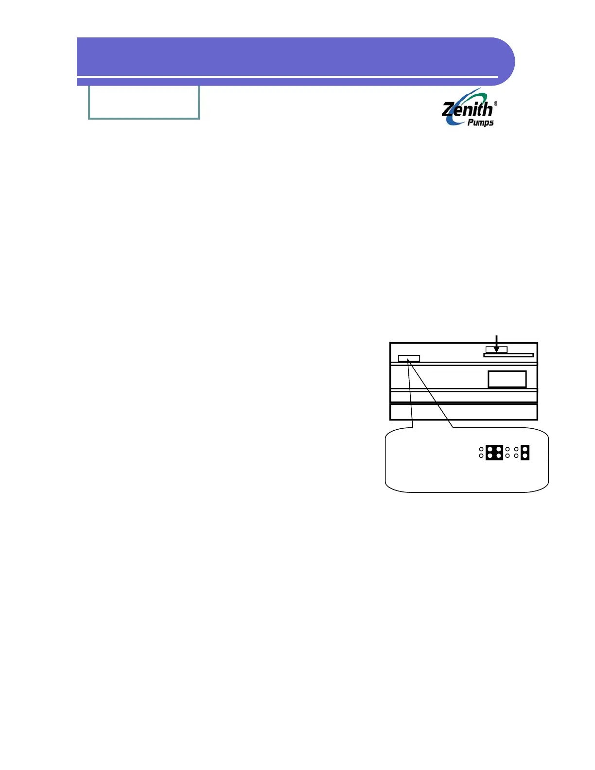
3. Locate Feedback Jumper as shown at left
4. Please check the jumper settings as shown at the left, and make changes as neces-
sary
• Disconnect the original feedback sensor
• Connect the wires from the flowmeter as follow:
Frequency signal wire - J3 Pin 5
Signal common wire - J3 Pin 6
Shield wire - J3 Pin 7
• Leave anything else unchanged as before
Analog I/O Board
(Not this jumper)
Heat Sink
Transformer
Jumper 1
(Feedback)
Feedback Jumper Location
3-wire Sensor (default):
Left