Page 31
TO GET ASSISTANCE, CALL: 919-774-7667
ZENITH PUMPS
Master/Follower System
1. Preliminary Action:
• Two individual ZeDrive systems are needed for forming
a master/follower system
• The following is only one example. For more detailed
system integration and configuration, please refer to
Chapter 5 in “ZeDrive and ZeTrol Manual”
• Master Reducer Gear Ratio — R
m
. If the pump is directly
coupled with the motor, the gear ratio R
m
=1
• Follower Reducer Gear Ratio — R
f
. If the pump is di-
rectly coupled with the motor, the gear ratio R
f
=1
• Motor maximum speed — V
M
(RPM), usually, 1800
(RPM)
• Master Pump Capacity — C
m
(cc/rev)
• Follower Pump Capacity — C
f
(cc/rev)
• Master Feedback Sensor Resolution — F
m
(No. of Teeth)
• Follower Feedback Sensor Resolution — F
f
(No. of Teeth)
2. Calculation:
2.1 Master Primary Setpoint — P
m
(cc/min)
P
m
(cc/min) = V
M
(RPM) / R
m
× C
m
(cc/rev)
2.2 Maximum Percent between Follower and Master — P
f
(%)
P
f
(%) = Follower Max. Flowrate (cc/min) / Master Max. Flowrate (cc/min)
= [ V
M
(RPM) / R
f
× C
f
(cc/rev) ] / [ V
M
(RPM) / R
m
× C
m
(cc/rev) ]
= [ R
m
/ R
f
] × [ C
f
/ C
m
]
3. Coding:
Check and change the following codes
For Master For Follower
Primary Setpoint, Eng. Unit Code 20 = P
m
Code 20 = P
f
Primary Display, Eng. Unit Code 22 = P
m
Code 22 = P
f
External Ref. Resolution, PPR Code 30 = F
m
Feedback Resolution, PPR Code 31 = F
m
Code 31 = F
f
Primary Max. External Ref. Speed, RPM Code 33 = V
M
Primary Max. Feedback Speed, RPM Code 34 = V
M
Code 34 = V
M
Primary Scaling Format Code 61 = 1 (Master) Code 61 = 2 (Follower)
Primary Display Format Code 63 = 1 (Master) Code 63 = 2 (Follower)
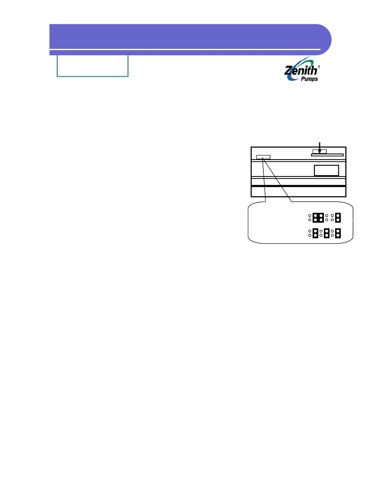
Analog I/O Board
(Not this jumper)
Heat Sink
Transformer
Jumper 1
(Feedback)
Feedback Jumper Location
3-wire Sensor (default):
Left
2-wire Sensor:
Left