Page 24
TO GET ASSISTANCE, CALL: 919-774-7667
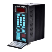
ZENITH PUMPS
Remote Monitoring Operation
1. Preliminary Action:
• To monitor system variables and control parameters,
you need a monitoring device, accepting either 4-20
(mA) or 0-10 (VDC) analog signal
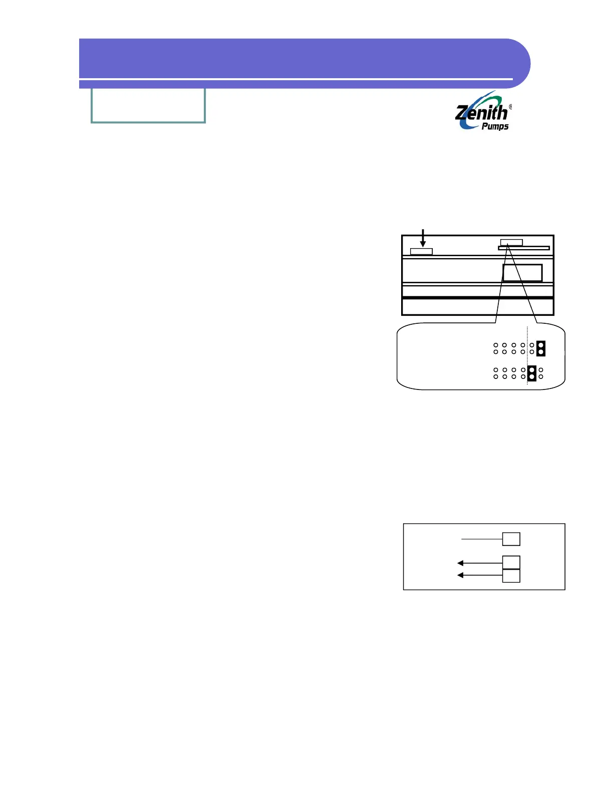
• Locate Analog Select Jumpers on “Control Board”:
1. Loosen up 6 screws on the back panel, and 2
screws located on the heat sink of ZeDrive
2. Remove the back panel, place ZeDrive as shown
at left. The top board is the “Control Board”, and
the bottom one is “Drive Board”
3. Locate Analog Select Jumper as shown at left
4. Depend on the signal, change the jumper set-
ting as shown at the left
2. Calculation:
None
3. Coding:
Check and change the following codes
• Code 80 = ?? (input corresponding code number for monitoring that specific variable)
Example: Code 80 = 40, it will monitor TACH, which is defined by Code 40
• Code 81 = ?? (defines the analog output range, usually the maximum value of the variable)
Example: Code 81 = 1800, when TACH = 1800 (RPM), it outputs 10VDC or 20mA
4. Wiring:
• Connect the wires of the monitoring device with the Ze-
Drive as shown at the left
5. Result:
• Provide an analog signal indicating the status of ZeDrive
variables and control parameters
• Support either 4-20 (mA) or 0-10 (VDC) analog signal
Analog Select Jumper
Analog Select Jumper Location
Heat Sink
Transformer
Feedback
(Not this jumper)
4-20 mA: (disregard)
Left
0-10 VDC:
(Default) Left
17
18
J4
7
J1
Shield
Common
Signal
To Device