Page 35
TO GET ASSISTANCE, CALL: 919-774-7667
ZENITH PUMPS
Calibrate Analog Input
NOTE:
In most instances, ZeDrive™ 2000 will come to you prepackaged in a control cabinet. The con-
troller will be mounted and all internal cabinet wiring will be complete.
The unit will also be programmed according to your specifications. The analog inputs and output
will have been calibrated for 4-20mA, unless otherwise specified. If re-calibration is desired for
some reason, such as using 0-10V signals, instead of 4-20mA, follow the appropriate procedure
below.
1. Preliminary Action:
• External device which supplies 0-10 (VDC) or 4-20
(mA) calibration signal to ZeDrive
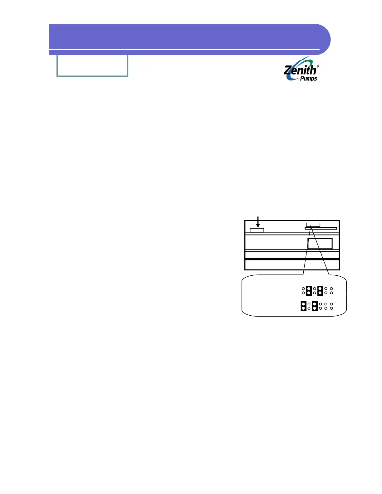
• Locate Analog Select Jumpers on “Control Board”:
1. Loosen up 6 screws on the back panel, and 2
screws located on the heat sink of ZeDrive
2. Remove the back panel, place ZeDrive as
shown at left. The top board is the “Control
Board”, and the bottom one is “Drive Board”
3. Locate Analog Select Jumper as shown at left
4. Depend on the signal, change the jumper set-
ting as shown at the left
2. Procedures:
2.1 Connect the analog calibration input source to J4-16(+) and J4-17 (-)
2.2 Select code C-85
2.3 Inject a “zero” signal (4mA or 0V)
2.4 Press the “.” button
2.5 Select code C-86
2.6 Inject a “span” signal (20mA or 10V)
2.7 Press the “.” button
Analog Select Jumper
Analog Select Jumper Location
Heat Sink
Transformer
Feedback
(Not this jumper)
4-20 mA:
Left
0-10 VDC:
(Default)
disregard