Page 7
TO GET ASSISTANCE, CALL: 919-774-7667
ZENITH PUMPS
WARNINGS:
• Danger of electrical shock or severe injury. Remove all jewelry prior to working on electri-
cal equipment
• Ensure electrical power is “OFF” before working inside the equipment
• Do not remove circuit protective devices, or any other components until power is turned
“OFF”.
NOTE:
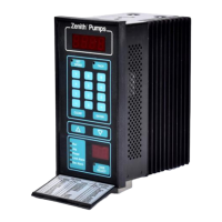
Mounting:
• Ensure the mounting location meets the environ-
mental conditions such as humidity and temperature
(refer to “ZeDrive Standard Specification” on Page
2) for ZeDrive
• Determine appropriate door or panel location and
make the panel cutout per figure shown at the left
• Remove (2 ea.) locking cam fasteners from ZeDrive
housing assembly, by removing (2 ea.) screws, one
from each cam fastener (top and bottom)
• Insert ZeDrive from the panel front and slide it in
until it is flush with the panel surface. Ensure that
supplied gasket is between the drive bezel and
panel surface.
• Re-install the locking cam fasteners from the rear of
the controller on top and bottom of housing assem-
bly. Rotate the cam fasteners so that ZeDrive pulls
securely against the panel surface.
• Tighten locking cam fastener (2 ea.) screws (top and
bottom)
Installation
The installation of this motor control must conform to area and local electrical codes. For infor-
mation, refer to the National Electrical Code (NEC) Article 430 published by the National Fire
Protection Association, or the Canadian Electrical Code (CEC). Refer to local codes as applica-
ble.
Zenith
®
Pumps
SET
SPEED
TACH
7
CLEAR
Run
Jog
Preset
Limit Alarm
Dev Alarm
8 9
6
5 4
1
3
2
-
.
0
ENTER
7.5”
3.6”
7.2”
3.9”
5.7”
Zenith
®
Pumps
SET
SPEED
TACH
7
CLEAR
Run
Jog
Preset
Limit Alarm
Dev Alarm
8 9
6
5 4
1
3
2
-
.
0
ENTER
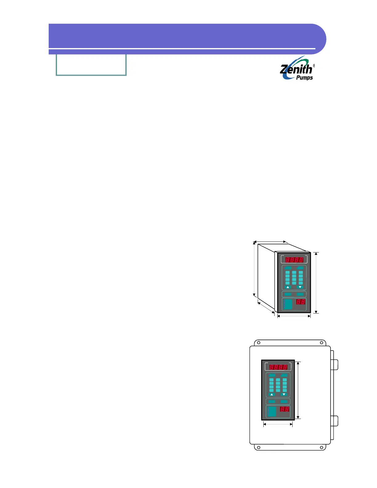
7.25”± .03
3.65”± .03
Panel Cutout