Page 6
TO GET ASSISTANCE, CALL: 919-774-7667
ZENITH PUMPS
Black
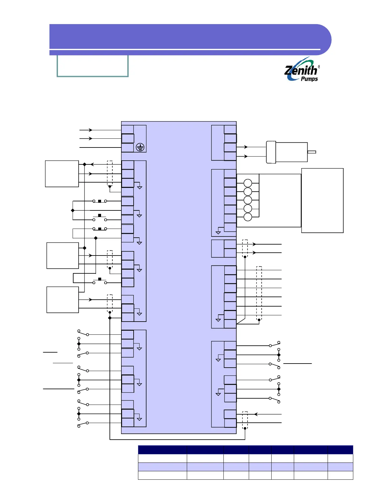
Standalone ZeDrive Wiring Diagram
DC Motor
Sensors Ch A+ Ch A - Ch B+ Ch B - Power
Magnetic Pickup
WHT or GRN ——- ——- ——- ——
Hall Effect
WHT or GRN ——- ——- ——- RED
Encoder
WHT ——- ——- ——- RED
Common
BLK & Shield
BLK & Shield
BLK & Shield
5
6
7
J2
1
5
6
7
11
12
13
14
15
2
3
4
16
8
9
10
1
2
3
4
8
9
10
11
12
13
14
17
18
1
2
3
4
5
6
7
4
5
6
1
2
3
7
8
9
10
11
12
13
14
15
16
17
Feedback
Sensor
Ext. Ref.
Sensor
Offset
Sensor
JOG
R-STOP
RUN
F-STOP
Spare
Closed
Open Loop
Ramp
Disable
Primary Setpt 2
Primary Setpt 1
Keypad
Lockout
Primary
Secondary
Secondary Setpt 3
Secondary Setpt 4
Local
Computer
Remote. Scroll Up
Remote. Scroll Down
Analog Signal Input
Analog Common
Red
White
Black
Red
White
Black
Red
White
A1
A2
+12V
+ TxD
-
+ RxD
-
COM (OPT)
Analog Signal Output
Analog Common
+
External
DC
Power
Supply
50V Max.
-
R
R
R
R
R
L1
Neutral L2
Chassis Gnd
Set By Switch! 115/230VAC
Zero Speed
High Alarm
Low Alarm
Dev Alarm 1
Dev Alarm 2
J3
J4
J2
J1
J4
J1
J4