Page 32
TO GET ASSISTANCE, CALL: 919-774-7667
ZENITH PUMPS
Master/Follower System (cont’d)
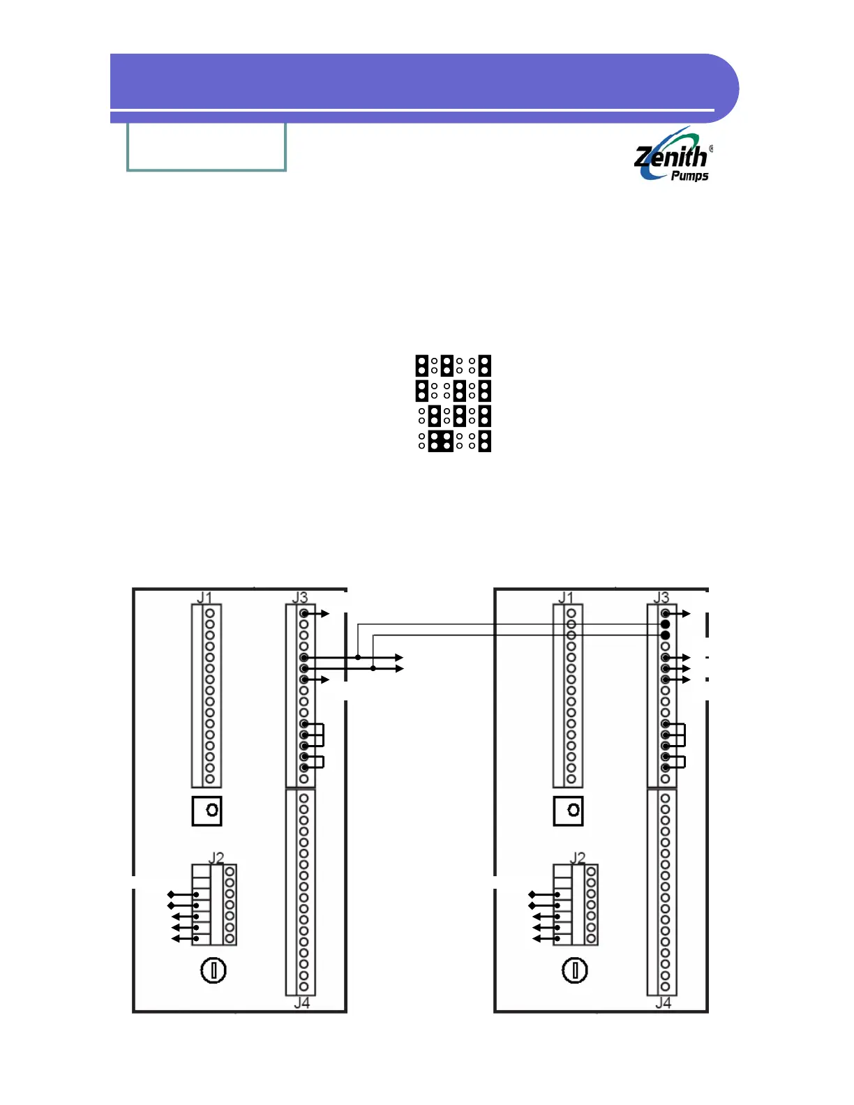
4. Wiring:
• Make sure the feedback jumper settings are correct and matched to the feedback sensors of
master and follower systems
Master Follower Jumper Settings
3-wire 3-wire left
3-wire 2-wire left
2-wire 2-wire left
2-wire 3-wire left
NOTE: Do not count bare wire (shield wire)
• Connect wires like the following illustration to form a master/follower system (for detailed
connection, please refer to page G-4 in “ZeDrive and ZeTrol Manual”
Follower ZeDrive
1
2
3
4
5
6
7
8
9
10
11
12
13
14
15
16
Red (for 3-wire)
Wht
Bare (Shield)
Blk
To
Feedback
Sensor
Jumpers
To AC
Power
To Follower Motor
To Follower
Feedback
Sensor
2
3
A2
A1
L1
N
G
1
2
3
4
5
6
7
8
9
10
11
12
13
14
15
16
Red (for 3-wire)
Wht
Bare (Shield)
Blk
To
Feedback
Sensor
Jumpers
To Master Motor
To AC
Power
Master ZeDrive
To Master
Feedback
Sensor