Jumpers
Jumpers
Table 2 – Model 6300 jumper settings
Jumper Position Purpose
JP3
JP4
A: Normal*
B: Non-inverted
These jumpers must be moved together to set the signal to inverted
or non-inverted for Link A.
JP5 Installed: Enable flashing
Removed: Write-protect*
Install the jumper during the procedure to add licenses. Otherwise,
the jumper should be removed.
JP6
JP7
A: Normal*
B: Non-inverted
These jumpers must be moved together to set the signal to inverted
or non-inverted for Link B.
JP8 Installed* Factory use only. Leave in the default position.
JP12
JP13
A: TTL levels*
B: RS232 levels
These jumpers must be moved together to set the levels for Link B.
JP16 Installed* Factory use only. Leave in the default position.
JP20
JP21
A: TTL levels*
B: RS232 levels
These jumpers must be moved together to set the levels for Link A.
JP24 A: Normal*
B: Failsafe
Toggles normal operation and failsafe operation. Failsafe operation
is only needed if the product’s firmware becomes corrupted. For
normal operation, leave the jumper in the default position A.
* = Default position
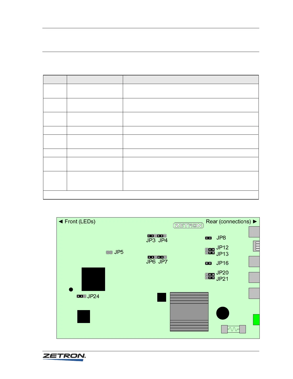
Figure 4 – Model 6300 jumper locations
19