Physical Installation
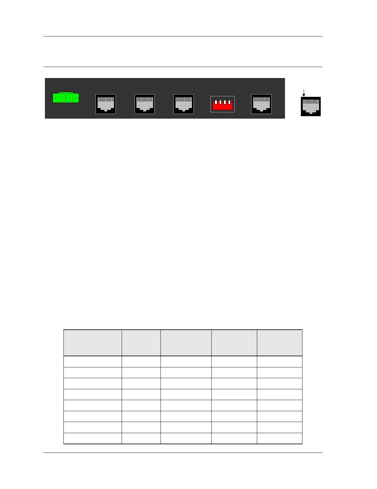
Connections
+13.5VDC/GND
A B C D
Tone Remote NetworkRadio A Radio B+13.5VDC/GND
A B C D
Balanced Audio
Network
Link 2Link 1
Pin 1
Power Port
Power should be applied only after jumpers and switches are set, and after the other
cables have been connected. Power should be removed if changing jumper or switch
settings.
The IP Gateway can be powered by your own power supply or by a Zetron-supplied
power supply. The IP Gateway accepts from +10.5 to +16 VDC with a minimum 500mA
rating. See Figure 3 on page 10 for the polarity.
• To use
your own power supply, a green screw terminal and cable are provided to
plug into the IP Gateway. Wire this connector/cable to your power supply.
• To power the IP Gateway from the Zetron supplied power supply (P/N
950-0923), simply plug it into the IP Gateway.
Balanced Audio Port
In order to provide for several connection scenarios, three cables are provided for this
port. Cable 709-7845 carries both Link A and Link B audio. Cables 709-7944 and
709-7945 carry one link each, using splitter 709-0153 to connect to the port.
Table 3 – Balanced Audio Port pinout
Signal
Balanced
Audio
Port Pin #
Cable
709-7845
Wire Colors
Cable
709-7944
Wire Colors
Cable
709-7945
Wire Colors
Link B TX+ Output 1 Grey N/C White/Orange
Link B TX– Output 2 Brown N/C Orange
Link A TX+ Output 3 Yellow White/Orange N/C
Link A RX+ Input 4 Green White/Blue N/C
Link A RX– Input 5 Red Blue N/C
Link A TX– Output 6 Black Orange N/C
Link B RX+ Input 7 Orange N/C White/Blue
Link B RX– Input 8 Blue N/C Blue
20 025-9631D.1