Do you have a question about the ZKTeco iFace Series and is the answer not in the manual?
Provides actual installation instructions only, referring to the User Manual for user instructions.
Important installation notices to prevent unit damage and ensure correct setup, emphasizing careful reading prior to use.
Install indoors away from windows and light fixtures. Optimal light intensity is 0-800 LUX.
Avoid direct sunlight, indirect sunlight, and proximity to light fixtures to ensure proper operation.
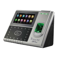
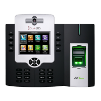
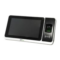
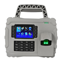
Identifies components on the front: LED light, TFT touch screen, Fingerprint Sensor, Baseline, RF Card Module, Touch Keypad, Camera.
Identifies components on the side: Power key, Reset key, and USB port.
Identifies components on the back: Battery slot, Power, TCP/IP, USB, connection terminal, and Loudspeaker.
Diagram illustrating the system's construction and connections between various devices.
Illustrates different communication methods: direct RS232/TCP/IP, RS485 network, and TCP/IP network.
Steps for affixing the paper template, drilling holes, mounting the plate, and securing the device cover.
Connects the door sensor to monitor door status and the exit button for releasing the door.
Details connections for alarm outputs (NC2, COM2, NO2) and door locks (NC1, COM1, NO1).
Covers Ethernet, RS232, and RS485 connections for device communication and networking.
Explains Wiegand output connection and the two methods for power connection (terminal and slot).
Instructions for hanging the iFace on the mounting plate and securing it with a screw from below.
Procedures for checking installation correctness, performing auto-check, registering a face template, and testing verification.
Procedure to restart the machine using the reset key by inserting a small tool into the reset hole.
Explains the anti-dismantle button's function to send an alarm signal when the device is tampered with.
Describes using the USB port for uploading and downloading data via a U disk.
Explains how the reserve battery switches to discharge state for power backup when the main power is cut.
Provides technical parameters for battery charge time, discharge time, working environment, storing environment, and cycle age.
Highlights dangers like explosion, leak, fire, and break due to improper handling of batteries.
The iFace Series is a biometric access control device designed for secure and efficient entry management. It integrates various authentication methods, including fingerprint, RF card, and facial recognition, making it a versatile solution for different security needs. The device is intended for indoor installation and is designed to operate within specific environmental conditions to ensure optimal performance and longevity.
The primary function of the iFace Series is to control access to a secured area. It achieves this by verifying user identities through multiple biometric and credential-based methods. The device can be connected to various peripheral equipment to form a comprehensive access control system.
Access Control: The iFace Series manages door locks, allowing entry only to authorized individuals. It supports both Normal-Open (NO) and Normal-Close (NC) lock types, providing flexibility for different door configurations. The device can be configured to power the lock directly or through independent adapters, depending on the lock's power requirements.
Time Ring Function: The device includes a time ring feature that allows it to trigger an electrical bell at appointed times. This can be useful for signaling shift changes, breaks, or other scheduled events. It supports both Normal-Open and Normal-Close bells.
Communication: The iFace Series offers multiple communication interfaces for integration with a PC and other network devices:
Door Monitoring: The device can be connected to a door sensor to detect the open/close status of a door. If the door is opened without authorization or not closed tightly, the device can trigger an alarm signal or a prompt warning.
Exit Control: An exit button can be connected to the device, allowing authorized individuals to exit the secured area from the inside. When the button is pressed, the door will open.
Alarm Function: The iFace Series includes an alarm connection that can be triggered by various events, such as unauthorized door openings or tampering attempts.
User Interface: The iFace Series features a TFT touch screen for intuitive operation. It also includes a touch keypad for data input and navigation. An integrated RF Card Module Read Section allows for card-based authentication.
Biometric Authentication: The device incorporates a fingerprint sensor and a camera for facial recognition, providing robust biometric authentication options.
Installation Flexibility: The device is designed for indoor installation and comes with a paper template to assist with accurate wall mounting. It is recommended to install the device at a height suitable for the average user.
Power Options: The iFace Series can be powered through a terminal connection or a slot connection using a DC12V adapter. It also includes a reserve battery for continuous operation during power outages.
Data Management: The device supports the use of a U flash disk for uploading and downloading data, providing a convenient way to manage user information and records.
Reset Functionality: In case of operation error or other issues that cause the machine to malfunction, a reset key is provided. A small tool can be used to press the reset button, allowing the device to restart.
Anti-Dismantle Protection: The iFace Series is equipped with an anti-dismantle button. If the back cover is removed or the device is tampered with, it will send an alarm signal through the terminal, enhancing security.
Reserve Battery Management: The device's reserve battery ensures continued operation during power cuts. Users are advised to ensure the battery is properly installed and to store it with full discharge capacity in a suitable environment (20℃±5℃). The battery has a cycle life of at least 300 charge and discharge cycles.
Wiring Guidelines: The installation guide provides detailed instructions for connecting peripheral equipment, emphasizing the importance of cutting off power before wiring to prevent damage. It also specifies guidelines for wire exposure, grounding, and cable selection to ensure stable and reliable connections.
Self-Test Function: After installation, the device offers an auto-test function to confirm that all components are correctly installed and functioning. This helps in verifying the installation before full operational use.
Diode for Lock Connection: When connecting an electric lock, it is crucial to parallel an FR107 diode to prevent self-inductance EMF from affecting the access control system. The diode must be installed with correct polarity.
Environmental Considerations: The manual provides recommendations for the installation environment, including optimal light intensity and distance from windows and light fixtures, to ensure accurate facial recognition and overall device performance. It also warns against using the device in harsh conditions or exposing it to water.
| Fingerprint Capacity | 500-3000 |
|---|---|
| Log Capacity | 100000 |
| Communication | TCP/IP, USB |
| Operating Temperature | 0 °C- 45 °C |
| Operating Humidity | 20%-80% |
| Verification Speed | <1 second |
| Weight | Varies by model |
| Face Capacity | 700 (Up to 3, 000) |