07 - 26 RT60 Rough Terrain Crane
7. 15 LUFFING OPERATION
The boom angle is controlled by the luffing cylinder, so as to have the working radius
changed.
The boom angle varies from -3° - 78°. The -3° boom angle provides great convenience for
jib assembly, line parts changing and boom head parts maintenance. The balance valves
fitted in hydraulic system can not only ensure the boom raised up and lowered down
steadily but also keep the boom stop at any required position.
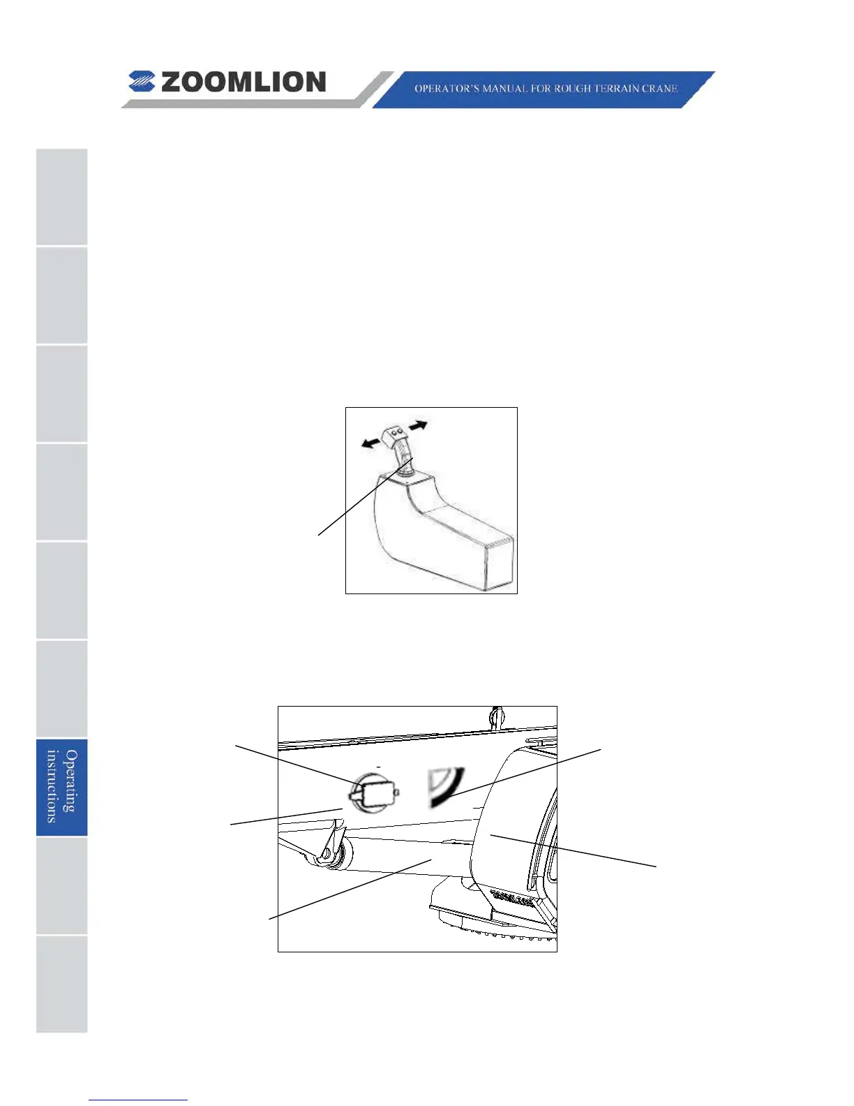
The luffing movements are controlled by the right joystick.
Luff speed increases as the joystick is moved further left or right. Luff speed also varies
with the engine speed. Do not change the luff speed abruptly to ensure stable crane
operations.
Fig. 07 - 21
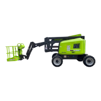
A boom angle indicator and a boom angle detector are fitted on the boom (see the flowing
figure). The boom angle indicator indicates boom angle relative to upper-structure and the
electronic angle detector transmits boom angle information to the rated capacity indicator,
which displays on the screen.
Fig. 07 - 22