RFSoC Data Converter Evaluation Tool User Guide 20
UG1287 (v2018.2) October 1, 2018 www.xilinx.com
Chapter 3: Hardware Design
DAC Control Switch
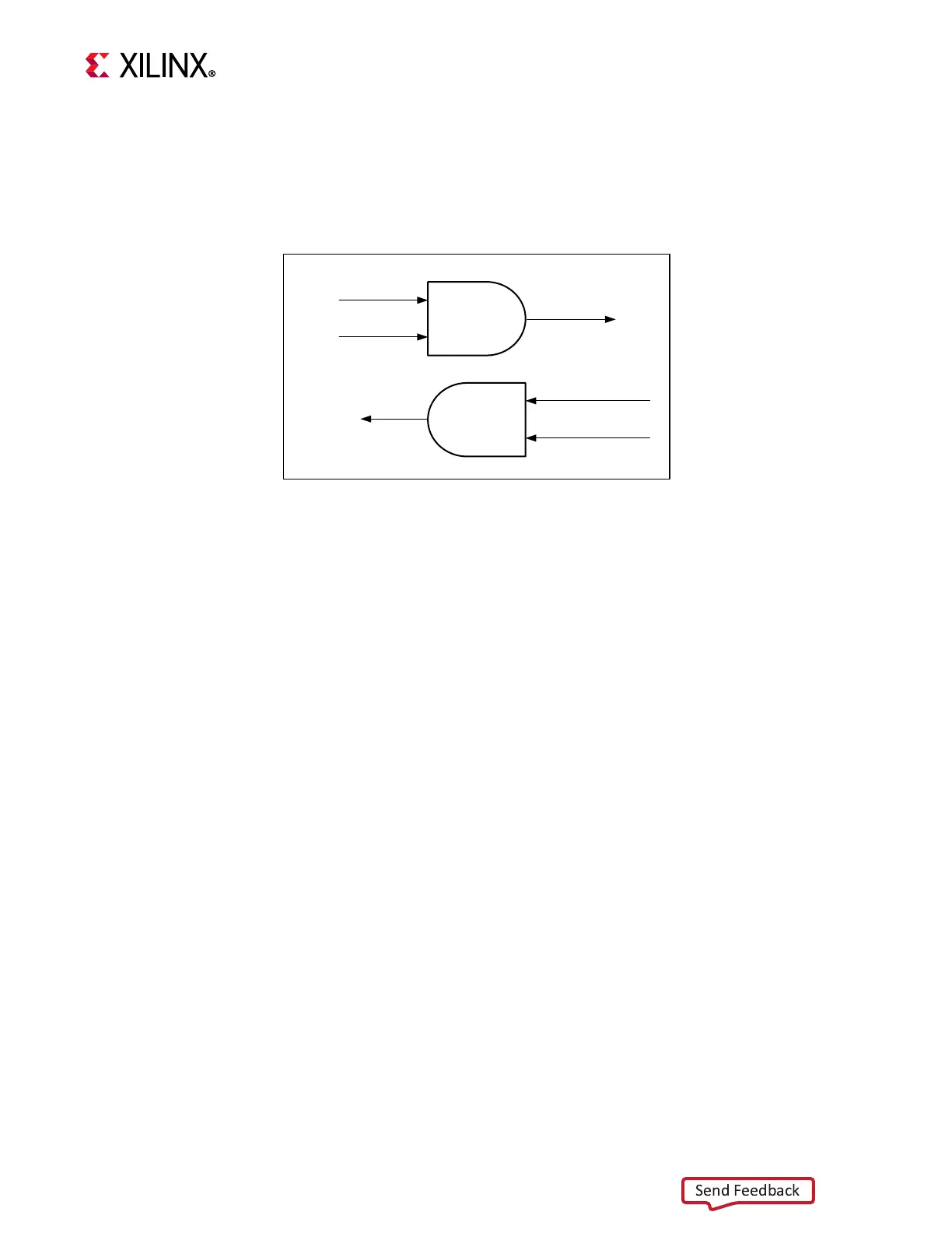
Control switch is control logic before the streaming interface is connected to the DAC. This
logic provides tight control over the streaming path and helps synchronize all the stream
interfaces at any given time. Figure 3-7 shows the control switch.
The channel control signal acts as a channel start/stop signal. This signal exists individually
for all channels and can be used to control each channel independently. This is done using
PS-GPIOs through the EMIO interface that are in turn controlled by software. The control
switch controls TVALID input to DAC and TREADY input to FIFO, as shown in Figure 3-7. See
GPIO Selection.
X-Ref Target - Figure 3-7
Figure 3-7: Control Switch
Channel Start
TReady Out to FIFO
Tready
Control
Switch
Control Switch
Tvalid In
Channel Start
Tvalid Out to DAC
X21238-090918
 Loading...