Chapter 1 Introducing the VMG
VMG3312-T20A User’s Guide
24
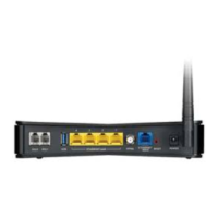
The following table describes the items on the rear panel..
1.6.6 The RESET Button
If you forget your password or cannot access the Web Configurator, you will need to use the RESET
button at the back of the device to reload the factory-default configuration file. This means that you will
lose all configurations that you had previously. The password will be reset to “1234”, and the LAN IP
address will be”192.168.1.1”.
1 Make sure the POWER LED is on (not blinking).
2 To set the device back to the factory default settings, press the RESET button for five seconds or until the
POWER LED begins to blink and then release it. When the POWER LED begins to blink, the defaults have
been restored and the device restarts.
1.6.7 Wall Mounting
You may need screw anchors if mounting on a concrete or brick wall.
3 Select a position free of obstructions on a wall strong enough to hold the weight of the device.
4 Mark two holes on the wall at the appropriate distance apart for the screws.
Be careful to avoid damaging pipes or cables located inside the wall
when drilling holes for the screws.
5 If using screw anchors, drill two holes for the screw anchors into the wall. Push the anchors into the full
depth of the holes, then insert the screws into the anchors. Do not insert the screws all the way in - leave
a small gap of about 0.5 cm.
If not using screw anchors, use a screwdriver to insert the screws into the wall. Do not insert the screws all
the way in - leave a gap of about 0.5 cm.
6 Make sure the screws are fastened well enough to hold the weight of the VMG with the connection
cables.
7 Align the holes on the back of the VMG with the screws on the wall. Hang the VMG on the screws.
Table 3 Rear Panel Ports
LABEL DESCRIPTION
Power Connect the power cable and press the power button to start the device.
Reset Press the button to return theVMG to the factory defaults.
LAN1 ~ LAN4 Connect computers or other Ethernet devices to Ethernet ports for Internet
access.
WAN Connect an Ethernet cable to the Ethernet WAN port for Internet access.
DSL Connect a RJ-11 cable to the DSL port for Internet access.
Table 4 Wall Mounting Information
Distance between holes 126 mm
M4 Screws Two
Screw anchors (optional) Two

 Loading...