4
RSMV Technical Guide
FIGURES AND TABLES
TABLES
Table 1: RSMV Controller Electrical and Environmental Requirements .................................................................. 7
Table 2: RSMV Inputs and Outputs ...................................................................................................................... 10
Table 3: Navigation Key Functions ........................................................................................................................ 14
Table 4: Coil Pressure/Voltage/Temp for Suction Pressure Transducers - R410A Refrigerant ............................. 23
Table 5: 0-5V Temperature Sensor - Voltage & Resistance for Type III Sensors .................................................. 24
Table 6: Head Pressure Transducer Chart ............................................................................................................ 25
FIGURES
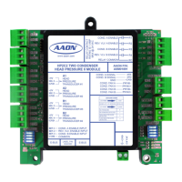
Figure 1: Refrigerant System Module Dimensions ................................................................................................... 6
Figure 2: RSMV Inputs Wiring ................................................................................................................................... 8
Figure 3: RSMV Outputs Wiring ................................................................................................................................ 9
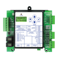
Figure 4: LCD Display and Navigation Keys ........................................................................................................... 14
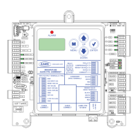
Figure 5: RSMV LED Locations .............................................................................................................................. 22
Figure 6: Prism 2 Condenser Conguration - Single Condenser Per Module ......................................................... 26
Figure 7: Prism 2 Condenser Conguration - Single Condenser Per Two Modules ............................................... 27
Figure 8: Prism 2 Condenser Conguration - Single Condenser for Three Modules .............................................. 28
Figure 9: Prism 2 Condenser Conguration - Single Condenser for Four Modules ................................................ 29
Figure 10: Prism 2 RSMV Conguration Screen ....................................................................................................... 30
Figure 11: RSMV Module A Compressor Type .......................................................................................................... 30