8
RSMV Technical Guide
WIRING
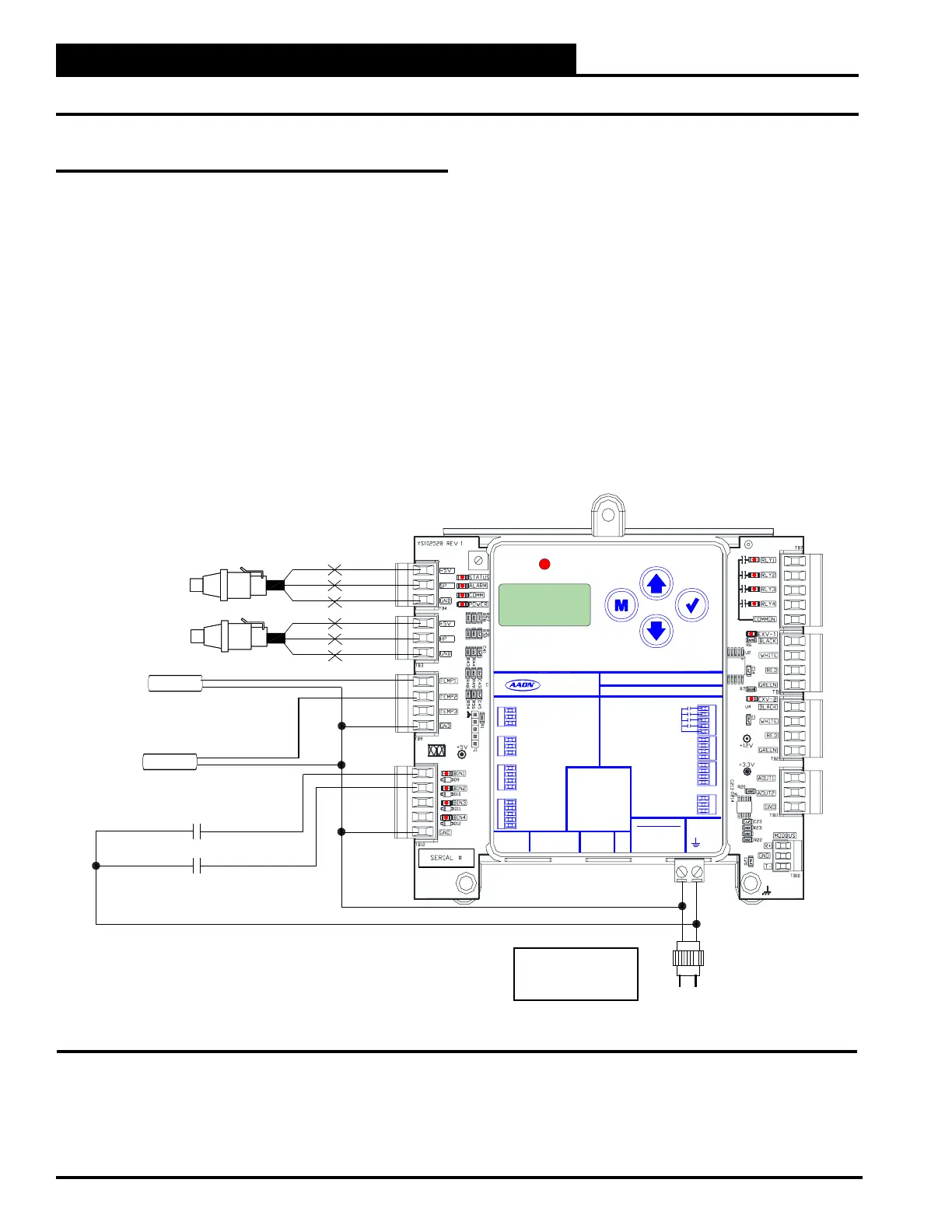
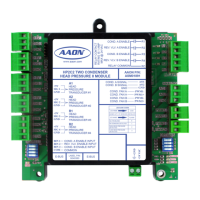
RSMV Inputs Wiring
RSMV Wiring
The RSMV is connected to the VCCX2 Controller. Up to 4 RSMV’s
can be connected, depending on the size of the system. There are
2 E-BUS Expansion Ports which allow the use of communicating
sensors and E-BUS Modules.
The RSMV provides 4 analog inputs, 3 binary inputs, 3 relays, and
4 analog outputs. See Figure 2, below for inputs wiring and Figure
3, page 9 for outputs wiring.
Suction Pressure Sensor Wiring
The Suction Pressure Transducer must be wired as shown in Figure 2,
below. It is required for all compressorized VCCX2 applications.
The Suction Pressure Sensor is used to measure suction pressure
at the HVAC unit’s DX evaporator coil suction line. This suction
line pressure is converted to saturated refrigerant temperature by
the RSMV Controller. This temperature is used by the RSMV to
accurately control the Expansion Valves to maintain Superheat
to provide optimum performance of the system. The saturated
refrigerant temperature is used to properly control the compressors
to maintain a given Suction Coil (Saturated) Temperature Setpoint.
In Cooling and Heat Pump mode, the VCCX2 resets the Suction
Coil (Saturated) Temperature Setpoint to maintain a given supply air
temperature setpoint. In Dehumidication mode, the Suction Coil
(Saturated) Temperature Setpoint is a user congurable setpoint that
can be reset based on indoor humidity levels.
SP
GND
+V
BK
RD
WH
HP
GND
+V
BK
RD
WH
SP
S
UCTION RESSURE
ENSOR
HP
S
(BY OTHERS)
EAD RESSURE
ENSOR
REFRIGERANT SYSTEM MODULE
FOR VFD COMPRESSORS
(RSMV)
COIL (SUCTION LINE)
TEMP. 2 SENSOR
TEMP1
GND
TEMP2
COMPRESSOR STATUS 1
COMPRESSOR STATUS 2
BIN1
BIN2
18-30 VAC
GND
Line Voltage
Size Transformer For
Correct Total Load.
RSMV = 18 VA
GND
COIL (SUCTION LINE)
TEMP. 1 SENSOR
AAON P/N: ASM01686
+24 VAC
GND
RELAY CONTACT
RATING IS 1 AMP
MAX @ 24 VAC
CONDENSER
COMP 1
COMP 2
ANALOG OUTPUTS
COMMON
RELAY OUTPUTS
LABEL P/N:
G042020
MOD COMP SIG
CONDENSER FAN SIG
GND
24 VAC POWER ONLY
WARNING! POLARITY
MUST BE OBSERVED
OR THE CONTROLLER
WILL BE DAMAGED
NOT USED
+5 V
+5 V
COIL TEMP 1
COMP STATUS 1
SP
HP
COIL TEMP 2
COMP STATUS 2
GND
GND
NOT USED
NOT USED
GND
TEMP 3
GND
COIL TEMP SENSORS
BINARYINPUTS
E-BUS
RSM FOR VFD COMPRESSORS
www.aaon.com
SUCTION PRESSURE SENSOR
HEAD PRESSURE SENSOR
E-BUS
EXPANSION
VALV E1
EXPANSION
VALV E2
WHITE
BLACK
RED
GREEN
WHITE
BLACK
RED
GREEN
ALARM
UP
DOWN
ENTERMENU
Figure 2: RSMV Inputs Wiring