32
RSMZ Technical Guide
APPENDIX A: TROUBLESHOOTING
RSMZ LED Diagnostics
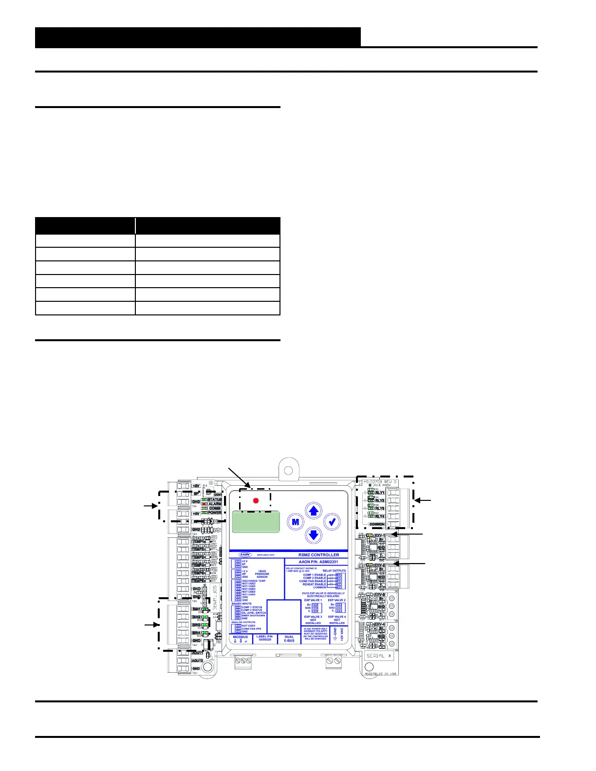
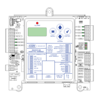
Using RSMZ LEDs to Verify Operation
The RSMZs are equipped with LEDs that can be used to verify
operation and perform troubleshooting. See Figure 9, this page
for the LED locations. The LEDs associated with these inputs and
outputs allow you to see what is active without using a voltmeter.
The LEDs and their uses are as follows:
STATUS - If the software is running, this LED will blink
according to what mode the RSMZ is in. See Table 7, this page.
ALARM (on board and above LCD display) - This red LED
will blink when there is an alarm present. The type of alarm will
display on the LCD display. The ALARM LED also blinks when
the expansion valve is initializing at startup.
COMM - Every time the module receives a valid E-BUS request
from the AAON unit controller, this LED will blink on and then
o, signifying that it received a valid request and responded.
POWER - This LED will light up to indicate that 24 VAC power
has been applied to the module.
Binary Input LEDs
BIN1 - This green LED will light up when Compressor 1 Status
contact is closed.
BIN2 - This green LED will light up when Compressor 2 Status
contact is closed.
BIN3 - This green LED will light up when the Oil Level Switch
is closed.
BIN4 - This green LED will light up when the Emergency
Shutdown contact is closed.
Relay LEDs
RLY1 - RLY4 - These green LEDs will light up when the relays
are enabled and will stay lit as long as they are active.
RSMZ Stepper Motor Valve LEDs
EXV-1 - This yellow LED will blink to indicate communication to
the DMQ. If the LED is on solid that indicates no communication
to the DMQ.
EXV-2 - This yellow LED will blink to indicate communication to
the DMQ. If the LED is on solid that indicates no communication
to the DMQ.
Figure 9: RSMZ LED Locations
No. of Blinks STATUS LED
1 O Mode
2 Cool Mode
3 Heat Mode
4 Reheat Mode
5 Force Mode
Fast Blink Emergency Shutdown
Table 7: STATUS LED Blink Codes
ALARM
UP
DOWN
ENTERMENU
Y
EXV-1
LED
STATUS
ALARM
COMM
POWER
LEDs
RELAY
LEDs
ALARM LED
EXV-2
LED