4
RSMZ Technical Guide
FIGURES AND TABLES
TABLES
Table 1: Electrical and Environmental Requirements ..........................................................................................................7
Table 2: RSMZ Inputs and Outputs .......................................................................................................................................8
Table 3: Subcool Monitor Inputs and Outputs .......................................................................................................................8
Table 4: Reheat Expansion Module Outputs ........................................................................................................................8
Table 5: Navigation Key Functions .......................................................................................................................................20
Table 6: Editing Key Functions ..............................................................................................................................................20
Table 7: STATUS LED Blink Codes ...................................................................................................................................... 32
Table 8: 0-5V Temperature Sensor - Voltage and Resistance for Type III Sensors .....................................................35
Table 9: 0-667 psi Transducer Chart .................................................................................................................................... 36
Table 10: Danfoss VFD Parameter Congurations .............................................................................................................. 37
FIGURES
Figure 1: RSMZ Dimensions ...................................................................................................................................................6
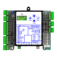
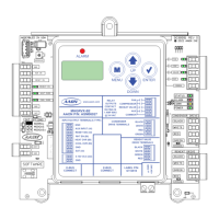
Figure 2: RSMZ Inputs Wiring - Modules 1, 2, 4, and 5 .......................................................................................................9
Figure 3: RSMZ Outputs Wiring - Modules 1, 2, 4, and 5 .................................................................................................. 10
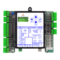
Figure 4: RSMZ Inputs Wiring - Modules 3 and 6 ............................................................................................................... 11
Figure 5: RSMZ Outputs Wiring - Modules 3 and 6 ............................................................................................................ 12
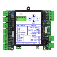
Figure 6: Reheat Expansion Module Wiring .........................................................................................................................13
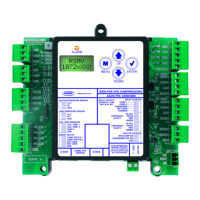
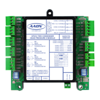
Figure 7: Subcool Monitor Module Wiring ............................................................................................................................14
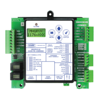
Figure 8: LCD Display and Navigation Keys ........................................................................................................................ 20
Figure 9: RSMZ LED Locations .............................................................................................................................................32
Figure 10: Subcool Monitor LED Locations ............................................................................................................................ 33
Figure 11: Reheat Expansion Module LEDs ..........................................................................................................................34
Figure 12: RSMZ Module Conguration .................................................................................................................................38
Figure 13: RSMZ Prism 2 Condenser Conguration ............................................................................................................38