Modules MC+1-3
70
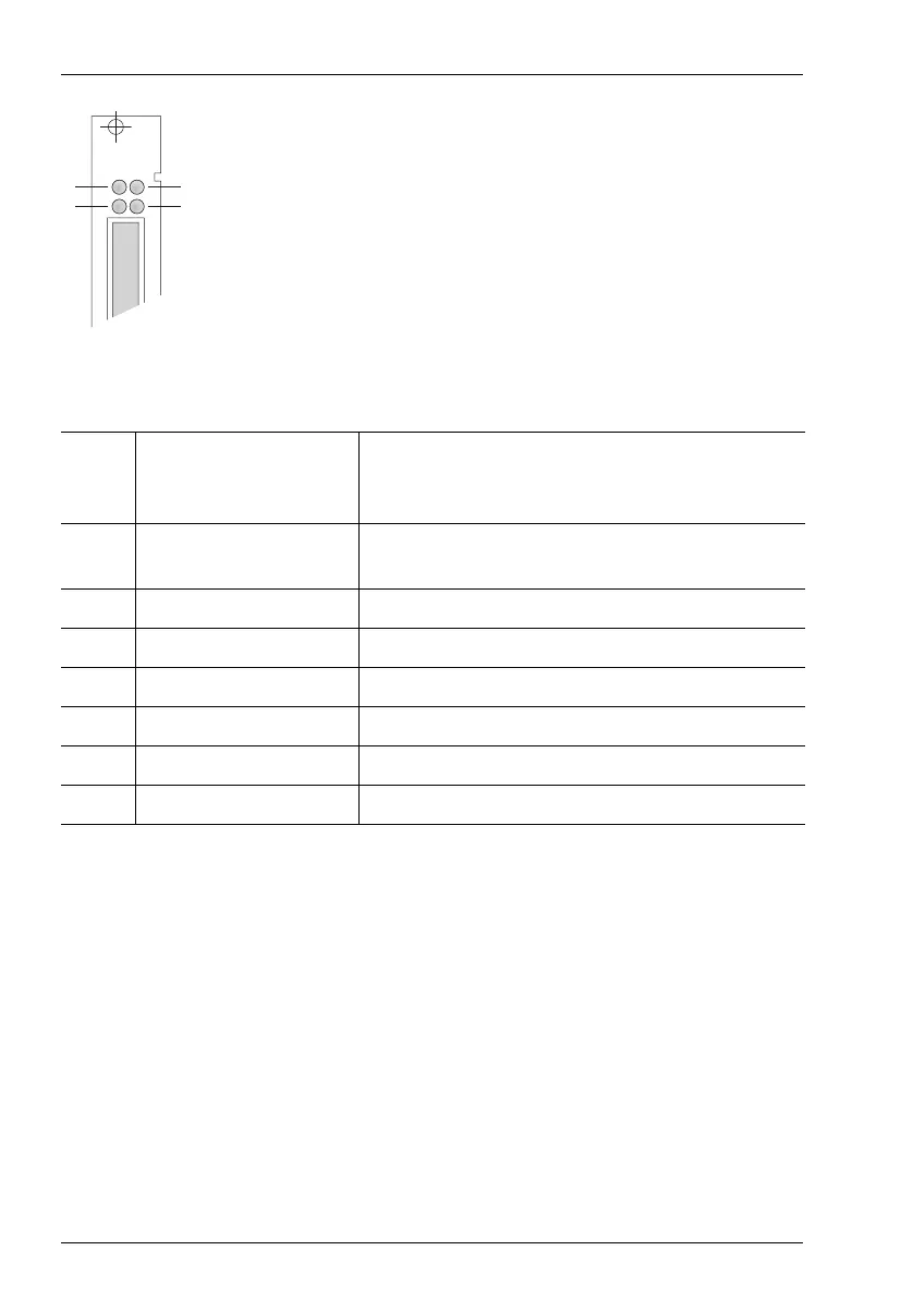
MC+1-3: LEDs
The LEDs indicate the following:
Operational Information
If you need to exchange the central control module, shut down the system first!
The OpenCom 510 must be disconnected from the mains supply (see Installing the
Central Control Module starting on page 29).
Do not pull the CompactFlash card during operation as this may cause data to be
lost!
A MC+1-3 central control module installed in a master system provides the fol-
lowing central resources:
■ 3 three-party conferences
LED 1: Flashing yellow New software is being loaded onto an interface
card (the corresponding interface card’s indica-
tor will be constantly red).
LED 2: Constantly green The central control module is operational (fli-
ckering is normal).
Flashing green/yellow The system software (firmware) is starting up.
Flashing yellow The booter is reloading.
Constantly yellow The system is booting.
Constantly red System fault
LED 3: – Not used
LED 4: Constantly green An Ethernet connection has been established.
MC+1-3
1
2
3
4