Interfaces and Connectible Terminals S
0
Ports
41
The following table explains the S
0
interface pin assignment.
5.2.1 Termination
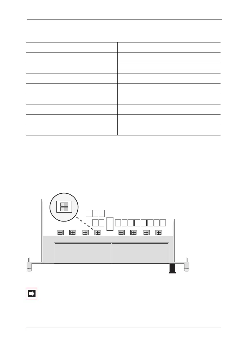
Each interface card has 16 DIP switches (S1 to S16, two per S
0
interface). The DIP
switches activate the required terminating resistors for the S
0
buses (100 ohms per
S
0
bus). In the default setting, all terminating resistors are activated (Default: on).
MX+S01-8: Location of DIP switches S1 to S16
Note: The following configuration information applies to ex-
ternal as well as internal S
0
interfaces.
Pin Number Assignment
1Not used
2Not used
3Send +
4 Receive +
5 Receive -
6Send -
7Not used
8Not used
1
2
ON