Interfaces and Connectible Terminals S
0
Ports
42
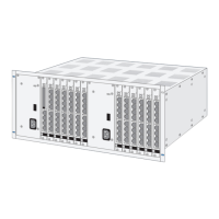
Bus Configuration: OpenCom 510 at the End of an S
0
Bus
If a OpenCom 510 is connected at the end of an S
0
bus, the terminating resistors of
the relevant S
0
interface cards must be activated.
In a typical configuration, the OpenCom 510 will be connected to the network ter-
mination for basic access (NTBA) with an externally switched S
0
port; therefore, all
terminating resistors of the interface card are activated in the default setting.
MX+S01-8: Terminating resistors activated
One end of the S
0
bus is terminated by the OpenCom 510; the terminating
resistors must be activated (DIP switches set to “on”).
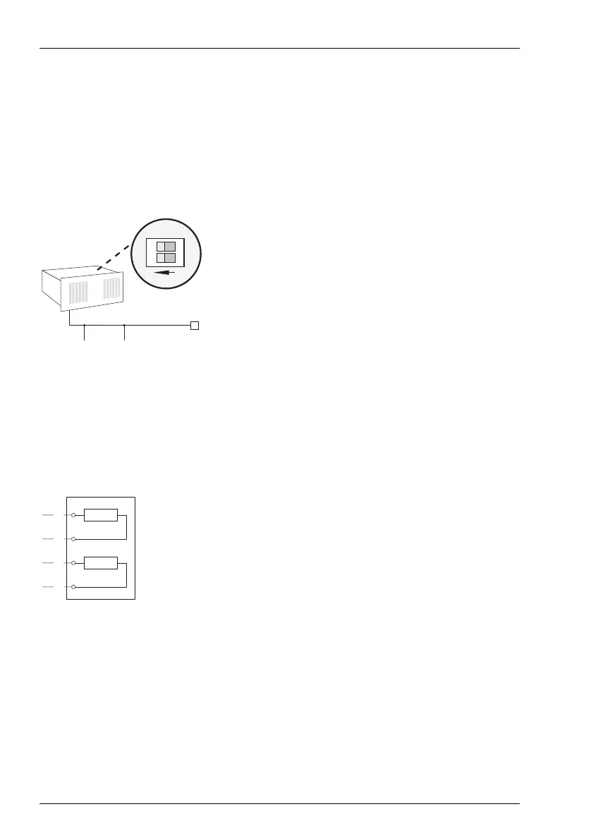
IAE = ISDN socket (German: “ISDN Anschluß Einheit”) or ISDN terminal.
TR = Terminating Resistor, the S
0
termination. The TR must be at the termination of
the line. This can also be done by an appropriately wired IAE.
Termination on an ISDN socket
The illustration Termination on an ISDN socket shows an IAE with integrated termi-
nating resistors.
Bus Configuration: OpenCom 510 in the Middle of an S
0
Bus
If a OpenCom 510 is connected in the middle of an S
0
bus, the terminating
resistors of the relevant S
0
interface cards must be deactivated.
1
2
ON
IAE IAE
TR
OpenCom 510
1a
1b
2a
2b
TR
TR