PBX Cascading Putting a Cascaded PBX into Operation
135
Cascaded PBX system
12.3 Putting a Cascaded PBX into Operation
Proceed as follows to put a cascaded PBX system into operation:
1. If you want to cascade two OpenCom 510 PBXs, you will need to set the frame
number using the DIP switches on the central control module.
To access the DIP switches, remove both central control modules (master and
slave systems); proceed as described in Installing the Central Control Module
starting on page 29.
2. Set the DIP switches of both modules as follows:
For the location of the DIP switches (S1and S2), refer to the illustration MC+1-3:
Top view.
3. Re-install the central control modules in the frames.
DIP Switch Settings
Frame as Master Frame as Slave
S1: open (switch set to “1”) S1: closed (switch set to “ON”)
S2: open (switch set to “2”) S2: open (switch set to “2”)
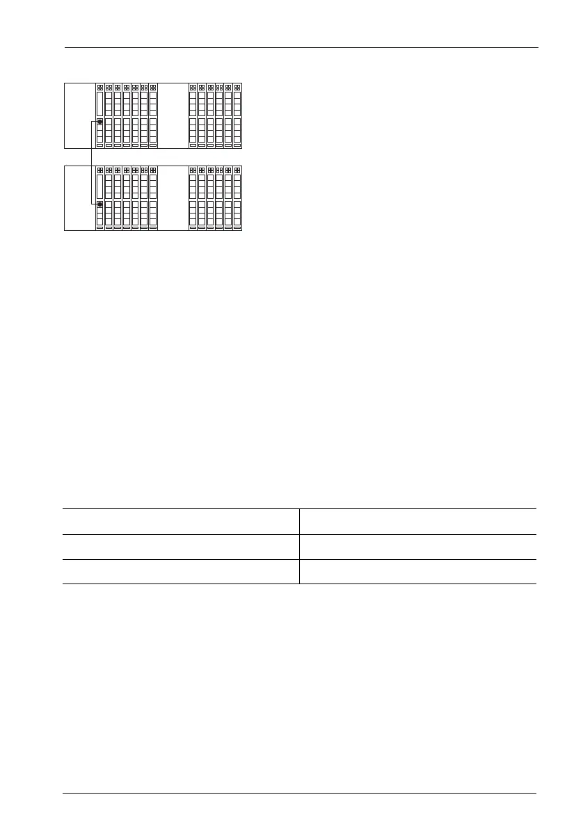
data lead (8 pins assigned, joined 1 to 1)
PBX 1 (Master)
BPX 2 (Slave)