Interfaces and Connectible Terminals S
0
Ports
43
1. Remove the interface card by following the instructions in Installing Interface
Cards starting on page 31.
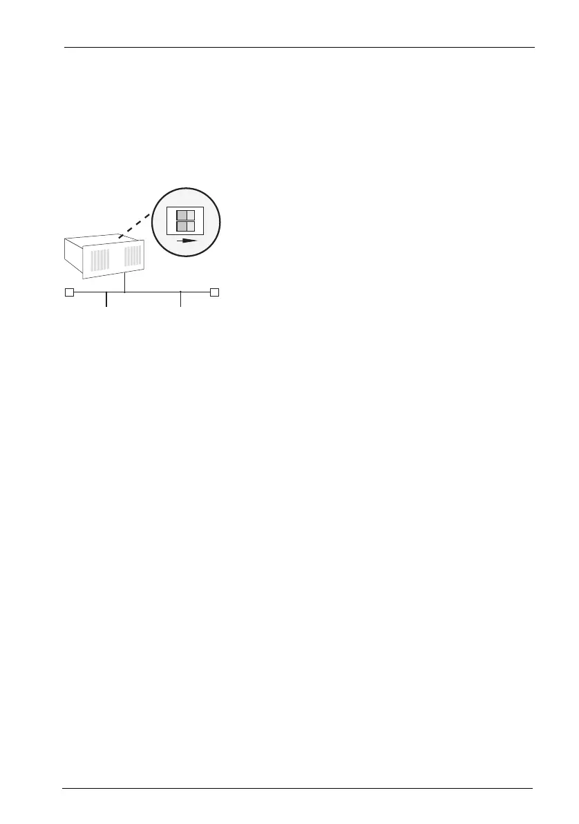
2. The DIP switches are protected by a plastic foil. Use a pointed tool such as a
screwdriver to slide the DIP switches down (see arrow in the illustration
MX+S01-8: Terminating resistors deactivated).
MX+S01-8: Terminating resistors deactivated
Both ends of the S
0
bus are terminated by terminating resistors; the terminating
resistors must be deactivated (DIP switches set to “1 2”).
5.2.2 External ISDN Ports (S
0
External)
You can connect the OpenCom 510 to the NTBA or to a second OpenCom 510 for
PBX cascading.
To connect the OpenCom 510 to the NTBA, wire pins 3, 4, 5, 6 of the NTBA and of
the OpenCom 510 1:1.
To directly connect two OpenCom 510 systems via the external S
0
ports, connect
the RJ45 sockets of the systems by means of a crossed twisted-pair cable. The dis-
tance between the two PBXs must not exceed 1000 metres (see also PBX Net-
working starting on page 140).
1
2
ON
IAE
TRTR
IAE
OpenCom 510