Modules MX+S01-8
77
Pin Assignment
For information on the S
0
interface pin assignment, refer to S0 Ports starting on
page 40.
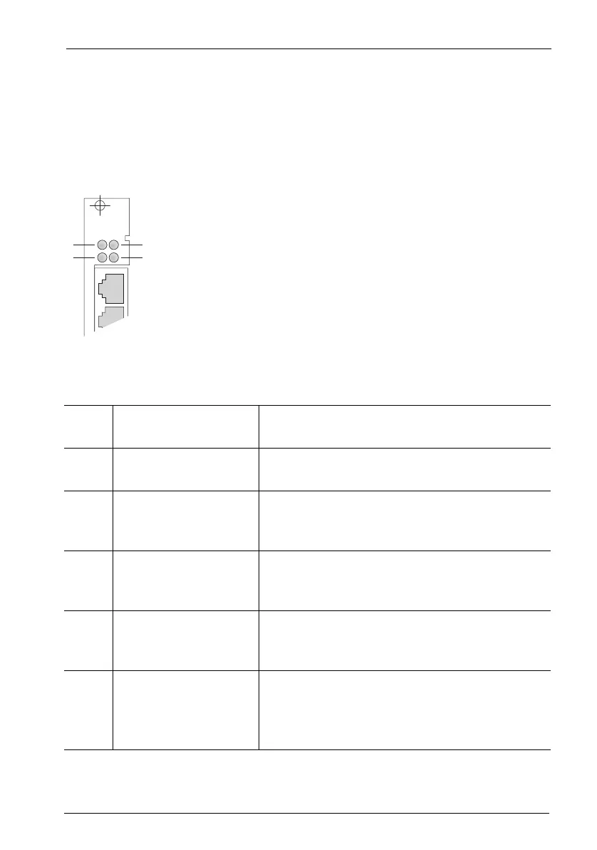
Indicators
There are four LEDs on the front of the MX+S01-8 interface card.
MX+S01-8: LEDs
The LEDs indicate the following:
LED 1: Constantly yellow At least one connection established through
the interface card is active.
LED 2: Constantly green The interface card is operational; the slot has
been activated (flickering is normal).
Flashing yellow The interface card is ready, but the slot has not
been activated or the interface card has not
been configured yet.
Constantly red New software is being loaded onto the interface
card. If the LED lights up red for an extended pe-
riod of time, there may be a fault.
LED 3: Constantly green The interface card is providing the system clock
signal (indicated only in the master system and
only on an interface card).
LED 4: Constantly yellow The interface card is running a combination of
subscriber and trunk connections, i.e. both in-
ternal and external S
0
interfaces have been con-
figured.
S0 1S0 2
MX+S01-8
1
2
3
4