Installing the drive 43
ACH550-01 User's Manual
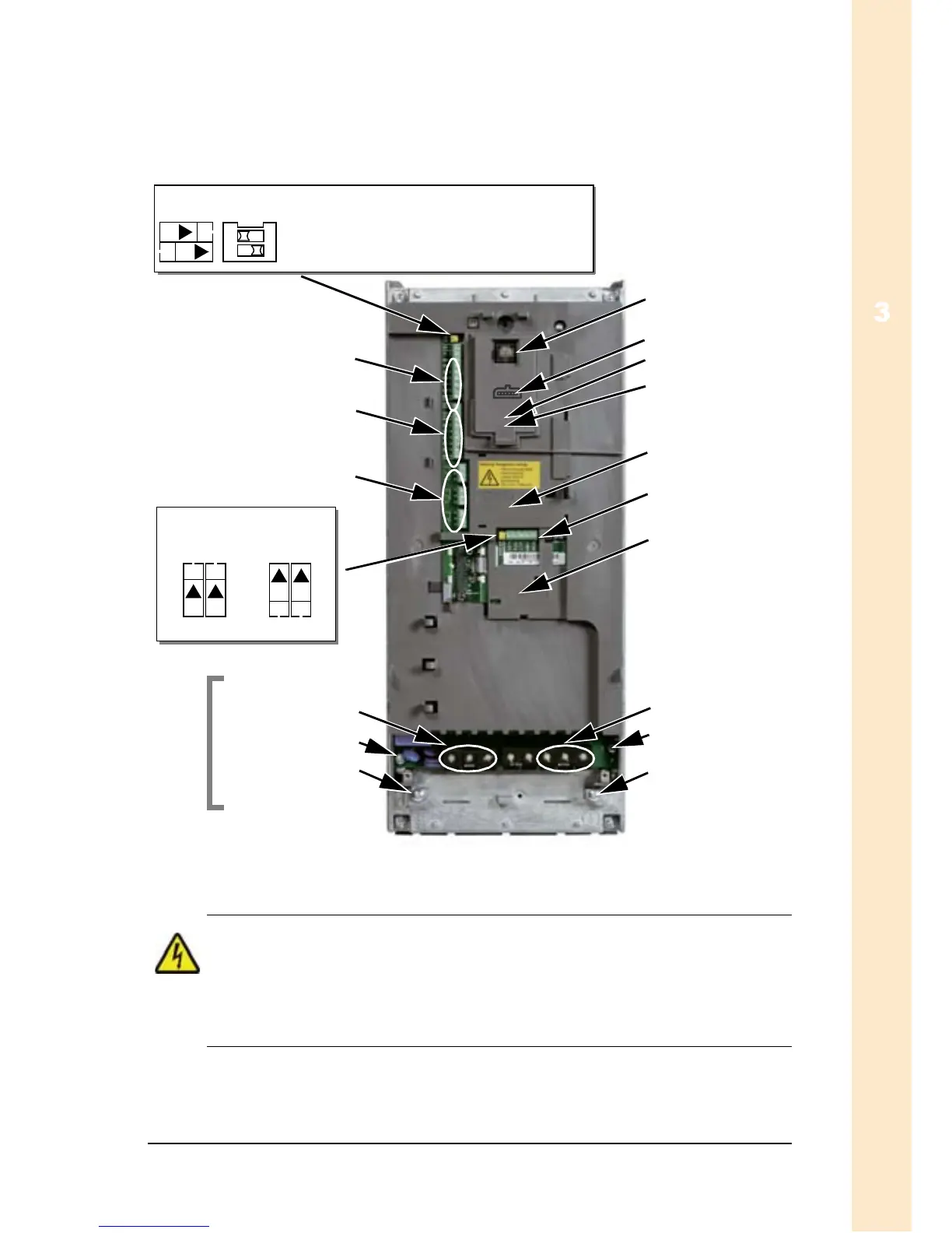
Overview of wiring installation (R1…R4)
The figure below shows an overview of the terminal layout for
frame sizes R1…R4.
WARNING! To avoid danger, or damage to the drive, on IT
systems, corner-grounded TN systems and residual current
circuit breakers, see section Disconnecting the internal EMC
filter on page 45.
J1
ON
ON
X0003
Panel connector
Power LED (Green)
Fault LED (Red)
Optional module 1
(Extended relay
output module)
Optional module 2
(Plug-in fieldbus)
Power output to motor
(U2, V2, W2)
EM3
GND
X1 – Communications
RS485 (Modbus,
FLN, N2, BACnet)
The figure shows the R3 frame size.
Other frame sizes have similar layouts.
Frame
sizes
R5…R6
differ.
See the
following
pages.
X1 – Analogue inputs and outputs
(and 10 V ref. voltage output)
X1 – Digital inputs
(and 24 V aux. voltage output)
X1 – Relay outputs
EM1
Power input
3-phase: U1, V1, W1
1-phase: U1 (live), W1
PE
J2
ON
J5
ON
J2
ON
J5
ON
J1 – DIP switches for analogue inputs (two switch types can be used)
AI1: (in voltage position) 0(2)…10 V
AI2: (in current position) 0(4)…20 mA
J2/J5 – DIP switches
for RS485 termination
off position on position
ON
12
J1
FlashDrop option
Artisan Technology Group - Quality Instrumentation ... Guaranteed | (888) 88-SOURCE | www.artisantg.com