60 Installing the drive
ACH550-01 User's Manual
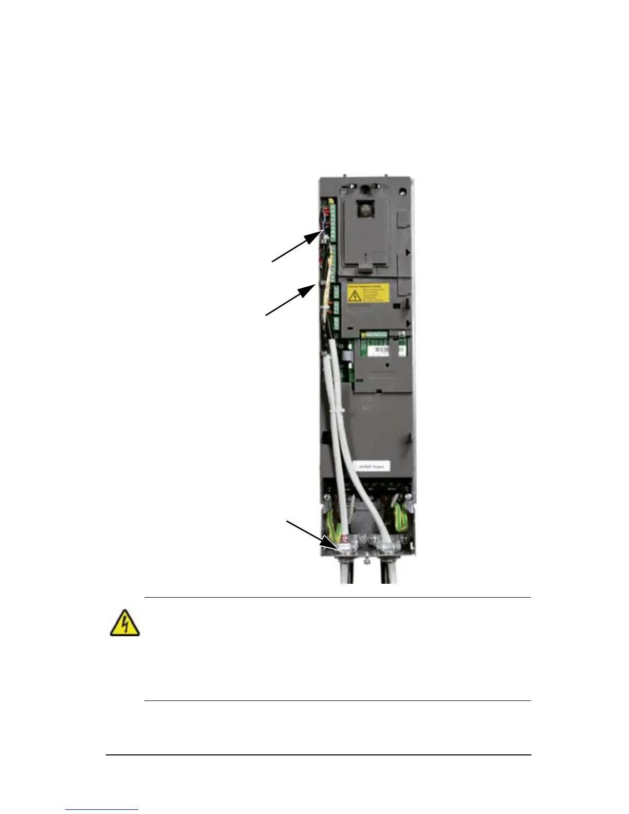
3. Route the control cable(s) through the clamp(s) and tighten
the clamp(s).
4. Connect the ground (earth) shield for digital and analogue I/
O cables at X1:1.
5. Strip and connect the individual control wires to the drive
terminals. See chapter Application macros and wiring.
6. Install the connection box cover (one screw).
WARNING! All ELV (Extra Low Voltage) circuits connected to the
drive must be used within a zone of equipotential bonding, i.e.
within a zone where all simultaneously accessible conductive parts
are electrically connected to prevent hazardous voltages appearing
between them. This is accomplished by a proper factory grounding.
For completing the connections, go to chapter Application
macros and wiring.