03 POWER ELECTRONICS AND CABINET FEATURES
3BHS213401 E01 REV H ACS1000 AIR-COOLED USER MANUAL 39/184
- Reduction of coasting down time, eg, for conveyor belts, fans, and pumps
- Emergency stops
The braking chopper cabinet connects to the right side of the drive as well as to the braking
resistors, which are external to the ACS1000 and not part of the product scope.
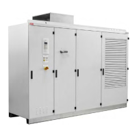
Figure 3-10: ACS1000 air-cooled with braking chopper (1)
The braking chopper is controlled and monitored by the ACS1000.
Figure 3-11: Principle diagram
(1) Rectifier
(2) Braking chopping
(3) Inverter
(4) Braking resistor
1
1
2 3
4

 Loading...