07 ELECTRICAL INSTALLATION
3BHS213401 E01 REV H ACS1000 AIR-COOLED USER MANUAL 96/184
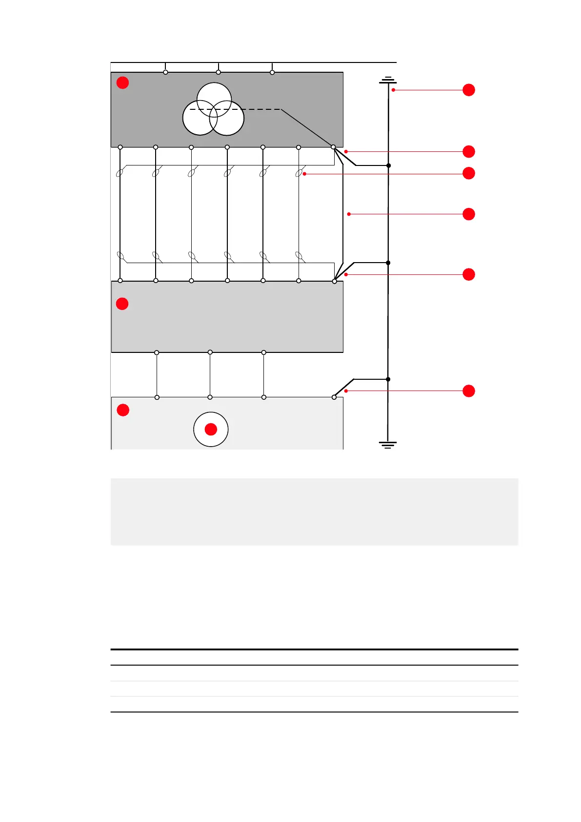
Figure 7-10: Grounding the drive system
7.5.3 Minimum creepage distance between cable and busbar
If spacers are used to connect a cable to a busbar, observe the minimum creepage distance.
Depending on the comparative tracking index (CTI) of the insulation material of the cable, the
following minimum creepage distances apply:
Table 7-2: Minimum creepage distance between cable and busbar
(1) Input transformer
(2) Drive
(3) Motor
(4) Earth electrode
(5) Ground cable
(6) Cable screen
(7) Equipotential bonding conductor
(8) Motor
PE
U
V
W
PE
2U1
ACS1000
2V1 2W1
1U1
1V1 1W1
PE
U2
V2
W2
U2
V2
W2
U1
V1 W1
U2
V2
W2
1
2
3
4
5
5
5
6
7
8
CTI Minimum creepage distance
1 600 63 mm
2 400 - 600 71 mm
3 175 - 400 80 mm