22 AQUAMASTER4 | ELECTROMAGNETIC FLOWMETER TRANSMITTER | OI/FET400-EN REV. D
…5 Installation
Grounding – FET410/430
IMPORTANT (NOTE)
The grounding arrangements shown in Figure 28 to
Figure 30 are applicable to both cathodic and non-
cathodic protected installations.
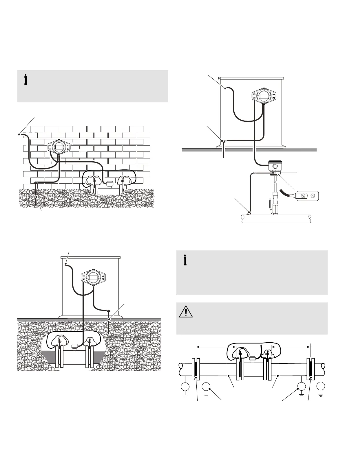
Figure 28
Mains power supply (option)
Earth (ground) rod
AquaMaster4 transmitter mounted in a chamber –
flanged sensor
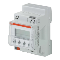
Mains power supply (option)
Earth
(ground) rod
Figure 29 AquaMaster4 transmitter mounted in a cabinet –
flanged sensor
Mains power supply (option)
Earth
(ground) rod
Bond probe
to pipe
Figure 30 AquaMaster4 transmitter mounted in a cabinet –
insertion sensor
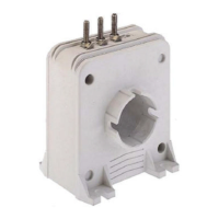
IMPORTANT (NOTE)
The grounding arrangements shown in Figure 31
are applicable ONLY to:
• cathodic protected installations
• installations where E2 and E3 are different to E1
CAUTION – DAMAGE TO EQUIPMENT
Incorrect installation will result in fault currents
flowing through the meter resulting in unstable
readings.
E
1
E
2
E
1
E
3
Conductive pipe
Cathodic potentials E1
MUST be equal
Insulator Insulator
Figure 31 Cathodic protected installations with different
cathodic potential generator