AQUAMASTER4 | ELECTROMAGNETIC FLOWMETER TRANSMITTER | OI/FET400-EN REV. D 31
Table 3 Connector input/output connections
(Modbus + Pulse / Modbus*)
Pin Signal Function Color (output cable)
A D0 Data D0 Violet
B D1 Data D1 Blue
C O/P COM Output common Yellow
D O/P2 Reverse pulses Red
E O/P3 Alarm output Brown
F O/P1 Forward pulses Orange
G 0V Signal ground Screen
* Refer to COI/FET400/MODBUS-EN for Modbus only
Pulse outputs
IMPORTANT (NOTE)
Outputs 1 and 2 are polarity-sensitive. The common
connection for these outputs is designated ‘COM’ and
is the negative connection.
OV* (–)
COM
O/P1 (+)
O/P2 (+)
COM (–)
O/P1 (+)
O/P2 (+)
Common
Input 1
Input 2
For example, telemetry, electronic and counters
Counter/Totalizers
Forward flow
Reverse flow
PLC or Datalogger
*Optional link for grounding floating
output – see Note above.
Figure 48 Pulse output connections
Alarm interface
IMPORTANT (NOTE)
Output 3 is not polarity-sensitive. The common
connection for these outputs is designated ‘COM’.
Figure 49
COM
O/P3
Common
Alarm input
Alarm output connections
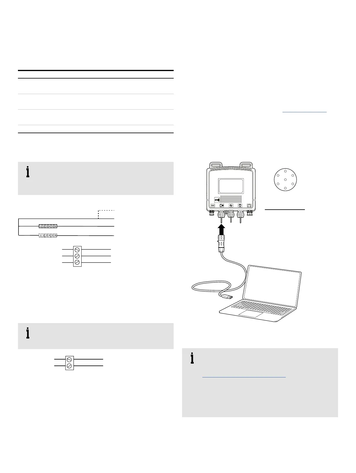
MODBUS connection
This section describes the AquaMaster4 MODBUS serial data
communications option and must be used in conjuction with
Communication Supplement COI/FET400/MODBUS.
Detailed specifications and recommendations for using and
implementing MODBUS communications are contained in the
following external publications – refer to www.modbus.org:
• "MODBUS over Serial Line – Specification and
Implementation Guide V1.02" – For hardware, cabling,
grounding and shielding
• "MODBUS Application Specification V1.1b"
Figure 50 MODBUS connection
IMPORTANT (NOTE)
A USB Comms lead driver is required when using
WEBC2100 – download from
www.ftdichip.com/FTDrivers.htm
The Modbus protocol is an unsecured protocol, as
such the intended application should be assessed to
ensure that these protocols are suitable before
implementation.
A
B
C
D
E
F
G
Ordering code
3KXF208400L0600
USB connector
Pin Modbus
A D0
B D1
C Not used
D Not used
E Not used
F Not used
G Common
MODBUS connector