24 AQUAMASTER4 | ELECTROMAGNETIC FLOWMETER TRANSMITTER | OI/FET400-EN REV. D
…5 Installation
Connections
DANGER – SERIOUS DAMAGE TO HEALTH
• The mains/line-powered transmitter option is not
fitted with a switch – an isolator such as a switch or
circuit breaker conforming to local safety standards
must be fitted to the final installation. It must be
fitted in close proximity to the transmitter, within
easy reach of the operator and marked clearly as
the isolator for the transmitter.
• Remove all power from supply, relay, any powered
control circuits and high common mode voltages
before accessing or making any connections.
• All connections to secondary circuits must have
insulation to required local safety standards. After
installation, there must be no access to live parts.
Use screened cable for signal inputs and relay
connections. Route signal leads and power cables
separately, preferably in an earthed (grounded)
flexible metal conduit.
WARNING – BODILY INJURY
• If the transmitter is used in a manner not specified
by the Company, the protection provided by the
equipment may be impaired.
• Replacement of the internal battery must be carried
out by an approved technician only.
• The transmitter conforms to Installation Category II
of IEC 61010.
• All equipment connected to the transmitter’s
terminals must comply with local safety standards
(IEC 60950, IEC61010-1).
Power supply connections
AquaMaster4 is available with three power options – battery,
AC with internal back-up and renewable with internal back-up.
Refer to Table 1 to identify valid combinations between
transmitter electronics and enclosure. NEVER mix and match
between different power options.
Table 1 Mix and match compatibility between transmitter
enclosure and transmitter electronics
Transmitter electronics power option
B (Battery) K (AC + internal
back-up)
R (Renewable+
internal back-up)
Transmitter
enclosure
power option
B/L
(Battery)
Yes No No
K
(AC + int’l back-up)
No Yes No
R
(Renewable+
int’l back-up)
No No Yes
See Transmitter overview on page 8 for power supply
options by transmitter type.
WARNING – BODILY INJURY
• Disconnect the supply from any cables that are
terminated on the transmitter.
• Electrical installation and earthing (grounding)
must be in accordance with relevant national and
local standards.
• The external earthing (grounding) boss must be
connected to an earthing (grounding) rod or to a
local electrical earth.
IMPORTANT (NOTE)
Power supply connections/earthing arrangements
are identical for cathodically-protected remote
transmitter systems. For cathodically-protected
integral transmitter systems, follow cathodic
installation practices.
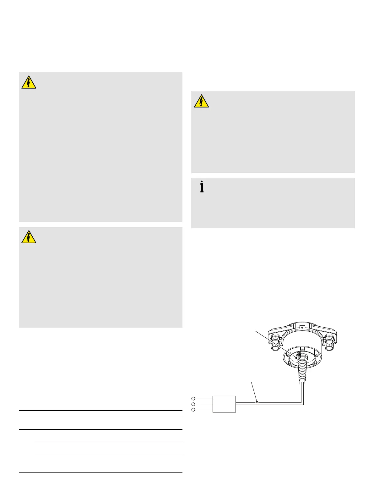
Mains power supply (remote transmitter)
Mains power requirements:
• 95 to 240 V AC, 50/60 Hz @ <3 VA
• Cable length 3 m (9.8 ft.)
• Protected by a fused isolator, rating – mains, anti-surge 3 A
Make connections as shown in Figure 36. Connect the external
earth (ground) boss to the local electrical earth or earth rod if
no electrical earth is available. Use a suitable wire with a cross
sectional area rated for >3 A.
External earth
(ground) boss
110 to 240 V AC
50/60 Hz
Color Connection
Green/Yellow Earth
Brown L1/L
Blue L2/N
Isolator/Fuse rating – mains, anti-surge, 3 A
Figure 36 Connecting a mains power supply
(remote transmitter FET41X/43X)