30 AQUAMASTER4 | ELECTROMAGNETIC FLOWMETER TRANSMITTER | OI/FET400-EN REV. D
…5 Installation
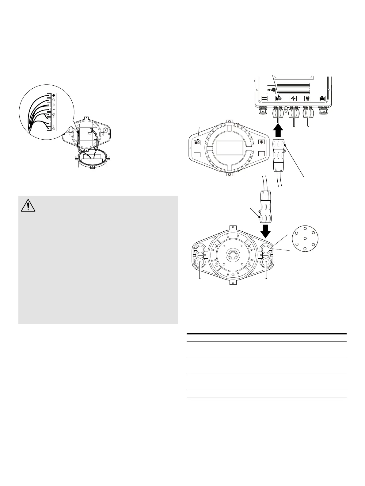
Integral sensor connections
Pre-wired sensor connections to the connector plug are shown
in Figure 46.
Figure 46 Integral sensor connections (pre-wired)
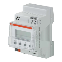
Input/Output connections
CAUTION – DAMAGE TO EQUIPMENT
• Refer to the Specification, Specification on page
63 for input/output ratings.
• Inductive loads must be suppressed or clamped to
limit voltage swings.
• Operation of outputs is programmable.
• External isolators are not normally required as the
pulse and alarm circuit is electrically-separated
from all other AquaMaster4 connections.
• Capacitive loads must be inrush current limited.
• Fully-floating pulse outputs may be subject to
static damage, for example connecting to a floating
datalogger, unless ‘COM’ is operated within its
galvanic isolation range (±35 V) from earth.
Input/Output connection socket
Figure 47 Input/Output connection socket (rear view)
Table 2 Connector input/output connections
(Sensus + pulse/pulse*)
Pin Signal Function Color (output cable)
A DATA Sensus Encoder Violet
B DATA CLOCK Sensus Encoder Blue
C O/P COM Output common Yellow
D O/P2 Reverse pulses Red
E O/P3 Alarm output Brown
F O/P1 Forward pulses Orange
G 0V Sensus Encoder Screen
*For pulse only connection, use pins C, D and F.
A
B
C
D
E
F
G
3KXF221400L0XXX /
3KXF208400L0600
3KXF221400L0XXX /
3KXF208400L0600
I/O
Pin view – I/O or
Modbus socket only
I/O