21
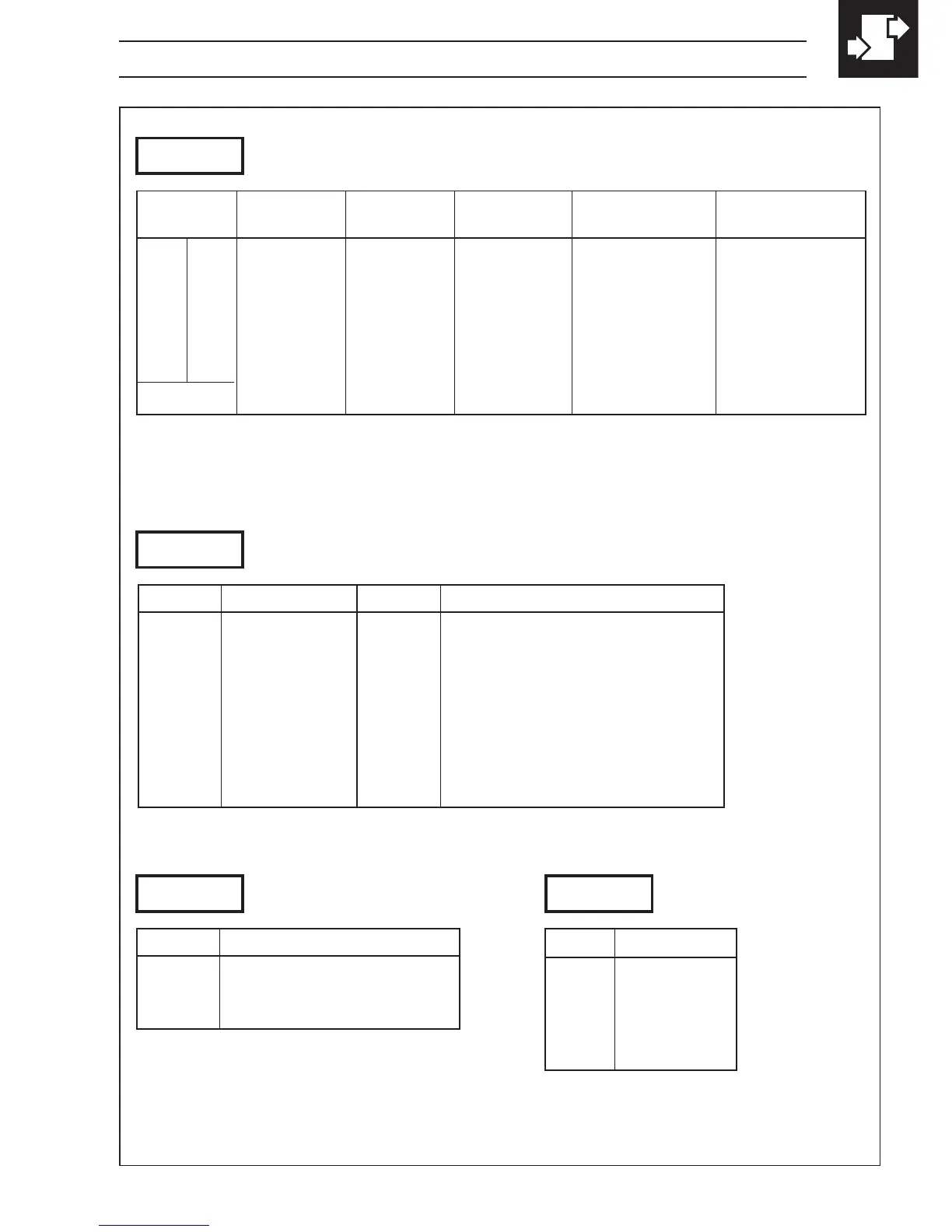
50Hz/60Hz Relay 1 Relay 2* Relay 3* Logic O/P Analog O/P
Source Source Source Source Source
1A Alarm 1 Alarm 2 Alarm 3 TCP** PV
2b Alarm 1 Alarm 2 Alarm 3 TWP** PV
3C TCP** Alarm 1 Alarm 2 TWP** PV
4d TWP** Alarm 1 Alarm 2 TCP** PV
5E Alarm 1 Alarm 2 Alarm 3 TCP** PV Average
U Custom Custom Custom Custom Custom
A 1KC0
A – Hardware Configuration
TCP = Totalizer Count Pulse TWP = Totalizer Wrap Pulse PV = Process Variable
b 1KC0
B – Input Type and Range Configuration
C 1KC0
D – Process Variable
Display Decimal Places
Display
0 xxxx
1 xxx . x
2 xx . xx
3 x . xxx
4 x . xxxx
d 1KC0
C – Temperature Units
Display Temperature Units
C Degrees C*
F Degrees F*
0 No temperature units
* Temperature inputs only
Display
b THC Type B
E THC Type E
J THC Type J
K THC Type K
N THC Type N
r THC Type R
S THC Type S
t THC Type T
P PT100 RTD
Display
1 0 to 20 mA
2 4 to 20 mA
3 0 to 5 V
4 1 to 5 V
6 0 to 50 mV
7 4 to 20 mA (square root lineariser)
U Custom Configuration
* Only available if the appropriate option board is fitted.
** Pulse energizes assigned relay
4 CONFIGURATION MODE…
Fig. 4.3 Hardware Configuration and Input/Output Ranges