1
Displays and Controls
• Displays and function keys
• LED Indication
• Error Messages
Operator Mode (Level 1)
• Operator menus for:
– Standard Indicator
– Totalizer/Batch Controller
– Maximum/Minimum/Average Indicator
Set Up Mode (Level 2)
• Alarm trip points
• Totalizer functions
Configuration Mode (Levels 3 and 4)
• Accessing the configuration levels
• Level 3
– Hardware assignment and input type
– Alarm types and hysteresis
– Operator functions and totalizer setup
– Digital input and serial communications
• Level 4
– Ranges and passwords
Installation
• Siting
• Mounting
• Electrical connections
8
GETTING STARTED
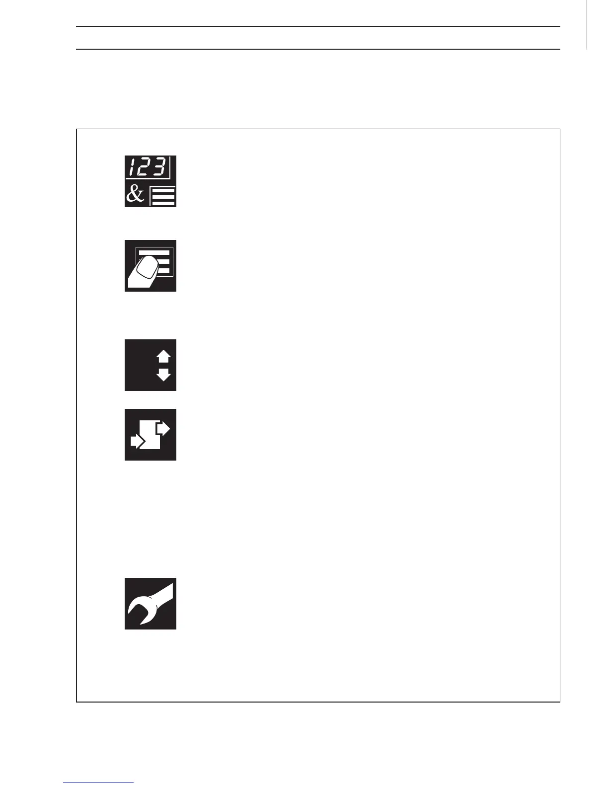
This manual is divided into 5 sections which contain all the information needed to
install, configure, commission and operate the COMMANDER 150. Each section is
identified clearly by a symbol as shown below.
Symbol Identification and Section Contents