20
LEVEL3
b 1KC0
A 1KC0
C 1KC0
d 1KC0
E 1203
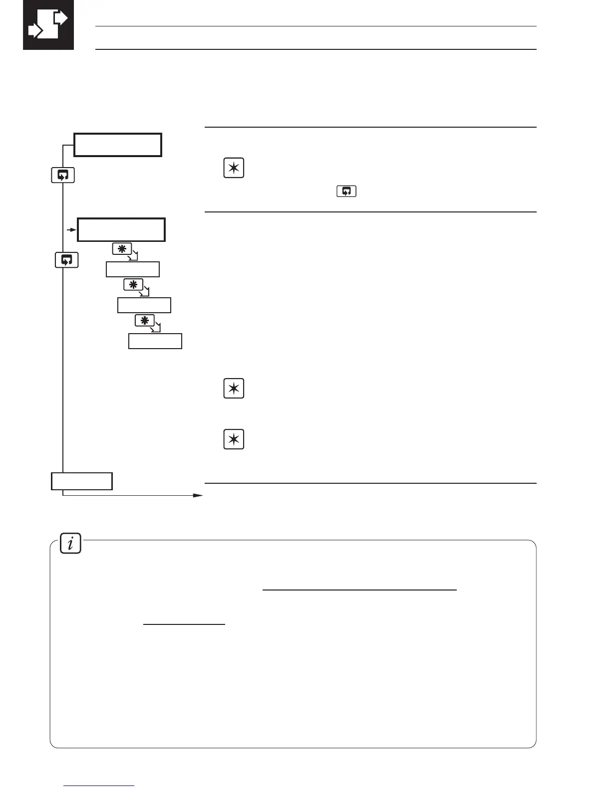
…4 CONFIGURATION MODE
Level 3
Note. To select to this frame from anywhere in
this level, press the
key for a few seconds.
'ABCD' Settings
The first character (
A, b, C or d) identifies the parameter
to be changed. The current setting is indicated by a
flashing letter. Parameter options are shown in Fig. 4.3.
A = Hardware configuration
b = Input type and range
C = Temperature units
d = No. of decimal points
Note 1. The temperature ranges default to their
maximum values when the input type is changed.
Note 2. For custom settings contact the local
distributor.
Continued on page 22.
4.3 Basic Hardware and Configuration (Level 3) – Fig. 4.3
4.3.1 Hardware Assignment and Input Type
Information.
Count High Calculation
Convert flow rate into units/sec =
actual engineering flow rate
flow range time units (in seconds)
Count High =
units/sec
resultant must be >0.001 and <99.999pps.
counter factor
Counter factor is the engineering value of the least significant digit shown on the
totalizer display – see Section 4.3.3.
Totalizer Count Pulse
The totalizer count pulse is on for a preset time of 250ms and off for a minimum of
250ms.