36
…5 INSTALLATION
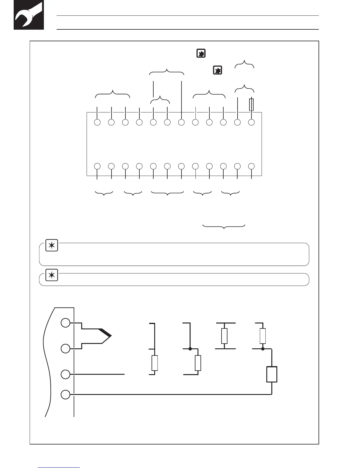
Note 1. The Analog Output and Logic Output use a common positive
terminal, capable of driving both outputs simultaneously.
Note 2. Fit arc suppression components if switching inductive loads.
Fig. 5.5 Electrical Connections
Analog
Output ✝
85 to 265V a.c.
C
Relay
Output 1
123456789101112
13
14
15
16
17
18
19
20
21
22 23
24
–
+
–
N/C
CN/O
Relay
Output 2
N/C
C
N/O
Digital
Input
+
–
RS485
TX
RS485
RX
+
RS485
or
Relay Output 3
N/C
C
N/O
+
+
–
–
Analog Input
(see below)
RTD1
Transmitter PSU
+
+
Logic Output
(18V at 20mA max.)
–
Not
Used
✝ 750Ω max. load
24V d.c.
+
–
L
N
1A
–
+
THC
millivolts
and volts
RTD –
3
rd
lead
RTD
+
3-lead
RTD
–
+
Milliamps
1
2
3
4
–
+
* Milliamps
2-wire
transmitter
RTD –
RTD –
RTD +
2-lead RTD
and resistance
**100Ω
* Using internal transmitter power supply
**100Ω
Tx
** Use 100Ω shunt resistor provided with instrument
1
2