Mechanical Information and Mounting 3-3MN448
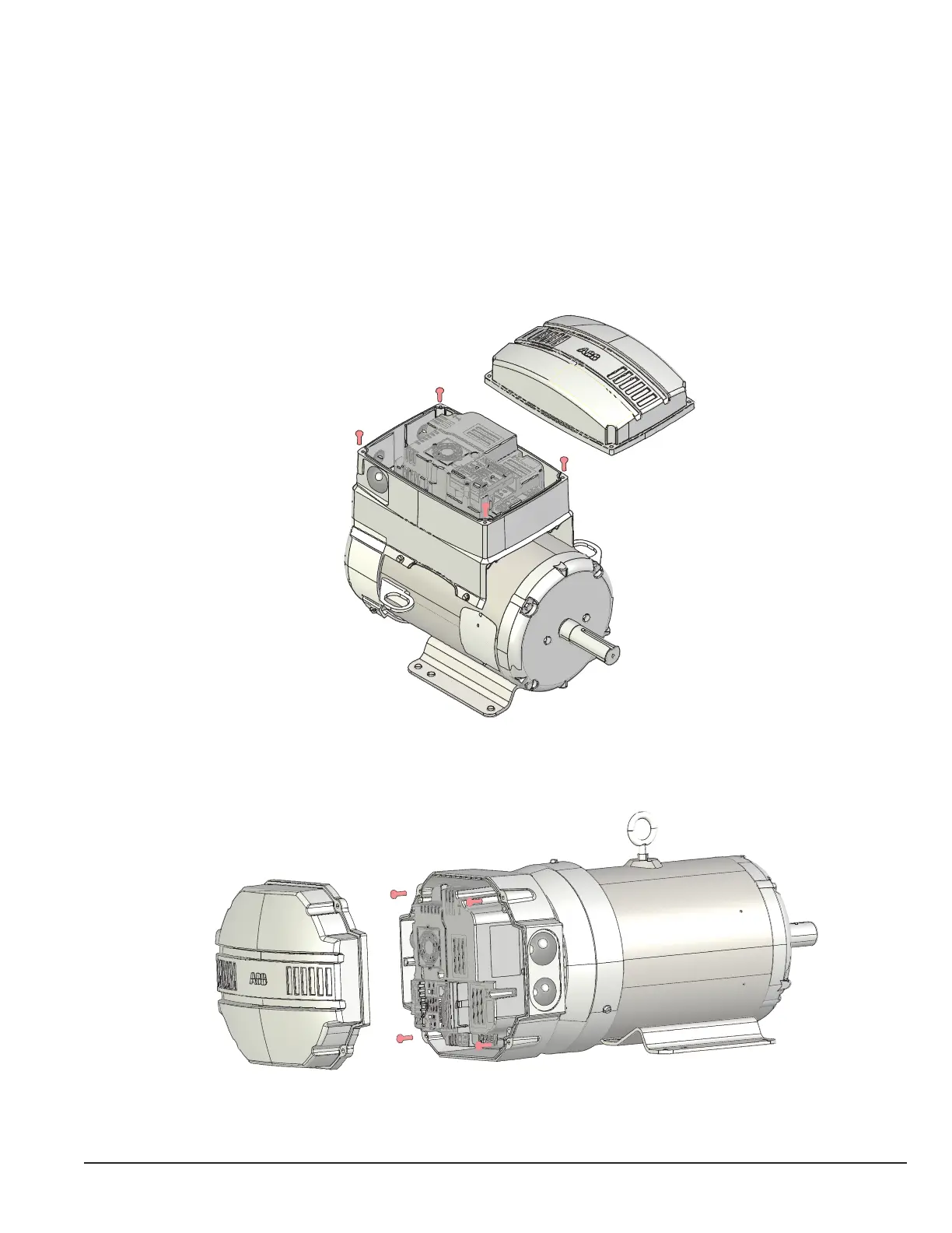
3.5 Removing Drive Cover
To connect power and signal wiring, the cover must be removed as shown below. For rst time setup prior to applying
power, remove the four retaining screws and carefully place them aside, then remove the cover to allow access to wiring the
drive modules.
Chapter 4 contains details on the internal power connections and Chapter 5 control wiring connections. See Chapter 9 for
examples of typical digital control program settings and example wiring diagrams.
Top Mount Drive Unit
Axial Mount Drive Unit