Control Wiring and Keypad Interface 5-1MN448
Chapter 5
Control Wiring and Keypad Interface
5.1 Control Terminal Connections
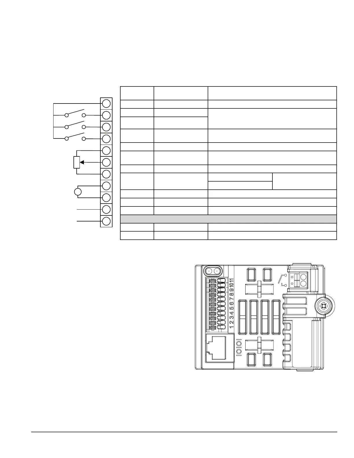
The gure below shows the I/O terminals.
Figure 5-1 Input and Output Terminals
V
2
8
4
1
5
6
7
3
9
10
11
Control
Terminal
Signal Description
1 +24V User Output +24V, 100mA
2 Digital Input 1 Positive logic
“Logic 1” input voltage range: 8V … 30V DC
“Logic 0” input voltage range: 0V … 4V DC
3 Digital Input 2
4
Digital Input 3 /
Analog Input 2
Digital: Logic 1 = 8 to 30V
Analog: 0 to 10V, 0 to 20mA or 4 to 20mA
5 +10V User Output +10V, 10mA, 1kΩ minimum
6 Analog Input 1 /
Digital Input 4
Analog: 0 to 10V, 0 to 20mA or 4 to 20mA
Digital: 8 to 30V
7 0V 0 Volt Common, internally connected to terminal 9
8 Analog Output /
Digital Output
Analog: 0 to 10V, 20mA maximum
Digital: 0 to 24V
9 0V 0 Volt Common, internally connected to terminal 7
10 Modbus RTU -
11 Modbus RTU +
RL1-A Relay Common
RL1-B Relay NO Contact Contact 250Vac, 6A / 30Vdc, 5A
5.2 Control Terminal Wiring
Analog signal (if connected): all analog signals should be
connected using suitably shielded, twisted pair cables.
Power and Control Signal cables should be routed sepa-
rately where possible, and must not be routed parallel to
each other.
Signal levels of different voltages e.g. 24 Volt DC and 110
Volt AC, should not be routed in the same cable.
Control Cable entries accept a single conductor,
Maximum size: 0.05 – 0.5mm2 / 20 – 26 AWG.