44 Electrical installation
General cabling instructions
• Arrange the bus cables as far away from the motor cables as
possible.
• Avoid parallel runs.
• Use bushings at cable entries.
Connecting the adapter module to the Ethernet
network
The network cable can be CAT5 or higher, and type UTP, FTP or
STP.
When CAT5 FTP or STP is used, the cable shield is connected to
the drive frame through an RC network. In FENA-01, it is possible
to change this connection by using jumper J1 located next to the
X1 connector.
• Position 1-2 connects the cable shield directly to the drive
frame.
• Position 2-3 connects the cable shield to the drive frame
through an RC network. This is the default setting of the
jumper.
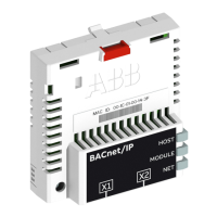
The figure below shows the location of jumper pin 1 on the FENA-
01 adapter module.