Placing the axis 3-4 assembly unit
NoteAction
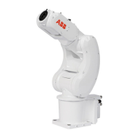
Mechanical stop, screw: 9ADA186-
23
Check the fixed mechanical axis limiting screw.
Replace if damaged.
1
xx2200000094
xx2200000542
Place the axis 3-4 assembly unit in place with the
axis-1 assembly unit.
Note
The axis 3-4 assembly unit is not secured with
the axis-1 assembly unit until the axis-2 drive unit
is refitted. Support the axis 3-4 assembly unit to
make sure it will not fall down.
2
Lay the assembly units on the workbench with
the axis-2 sleeve facing upwards.
3
Axis-2 sleeve: 3HAC074872-001Refit the axis-2 sleeve.
Note
Make sure the screw holes are aligned and the
sleeve is evenly refitted.
4
Screw: M3x10 12.9 Lafre
2C2B/FC6.9 (9 pcs)
Tightening torque: 1.5 Nm
xx2200000070
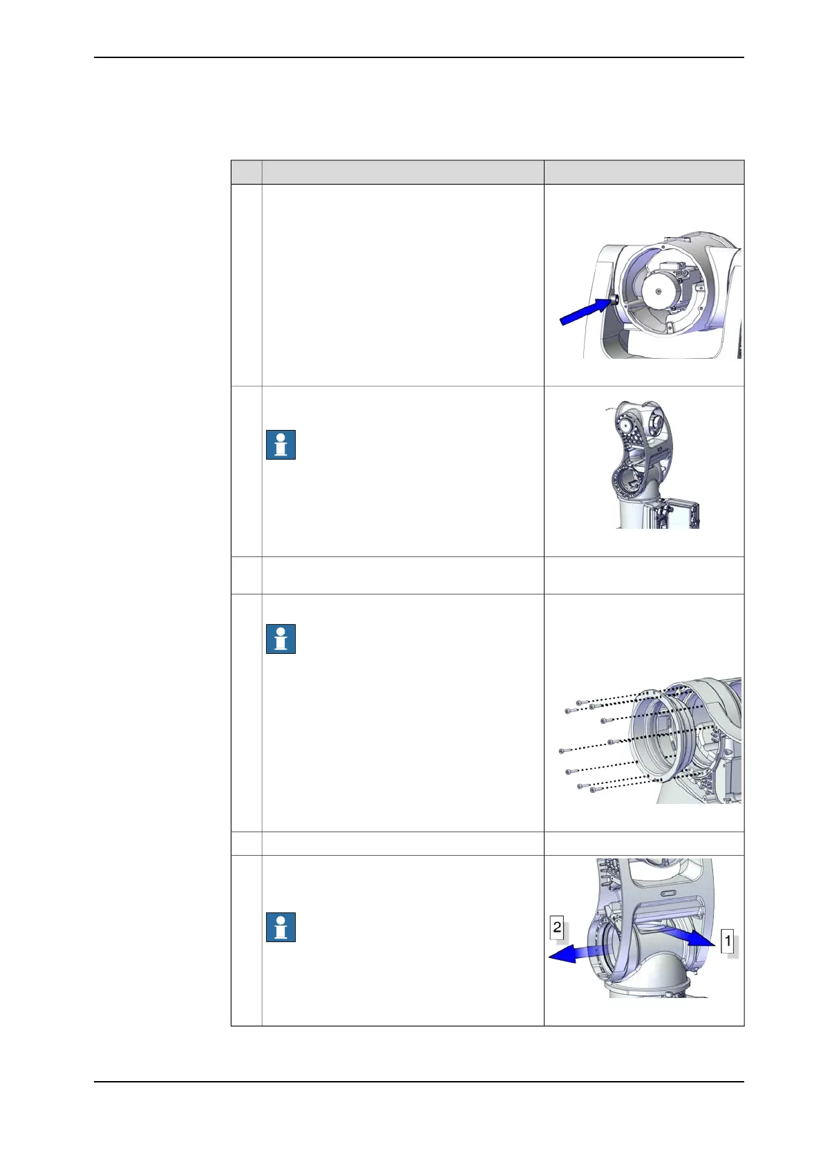
Turn the assembly units to stand position.5
xx2200000095
Route the cable package out from the swing top
first (direction 1) and then out from the axis 1 as-
sembly unit (directions 2).
Note
Note the cable routing direction, that is, out from
the right side of the robot (the side where the axis-
2 sleeve will be fixed).
6
Continues on next page
Product manual - IRB 1010 207
3HAC081964-001 Revision: B
© Copyright 2022 ABB. All rights reserved.
5 Repair
5.4.3 Replacing the axis 3-4 assembly unit
Continued