Maximum allowed arm load depends on center of gravity of arm load and robot
payload.
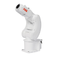
Holes for fitting extra equipment
424,5
250
45
138
190 185
208
125
20
70
185
C
419
B
D
290
A
18
(4x)M3x5.5
DETAIL C
18
(2x)M3x5.5
DETAIL A
18
(2x)M3x4.5
DETAIL B
135
184
119
18
(4x)M3x5.5
DETAIL D
xx2200000189
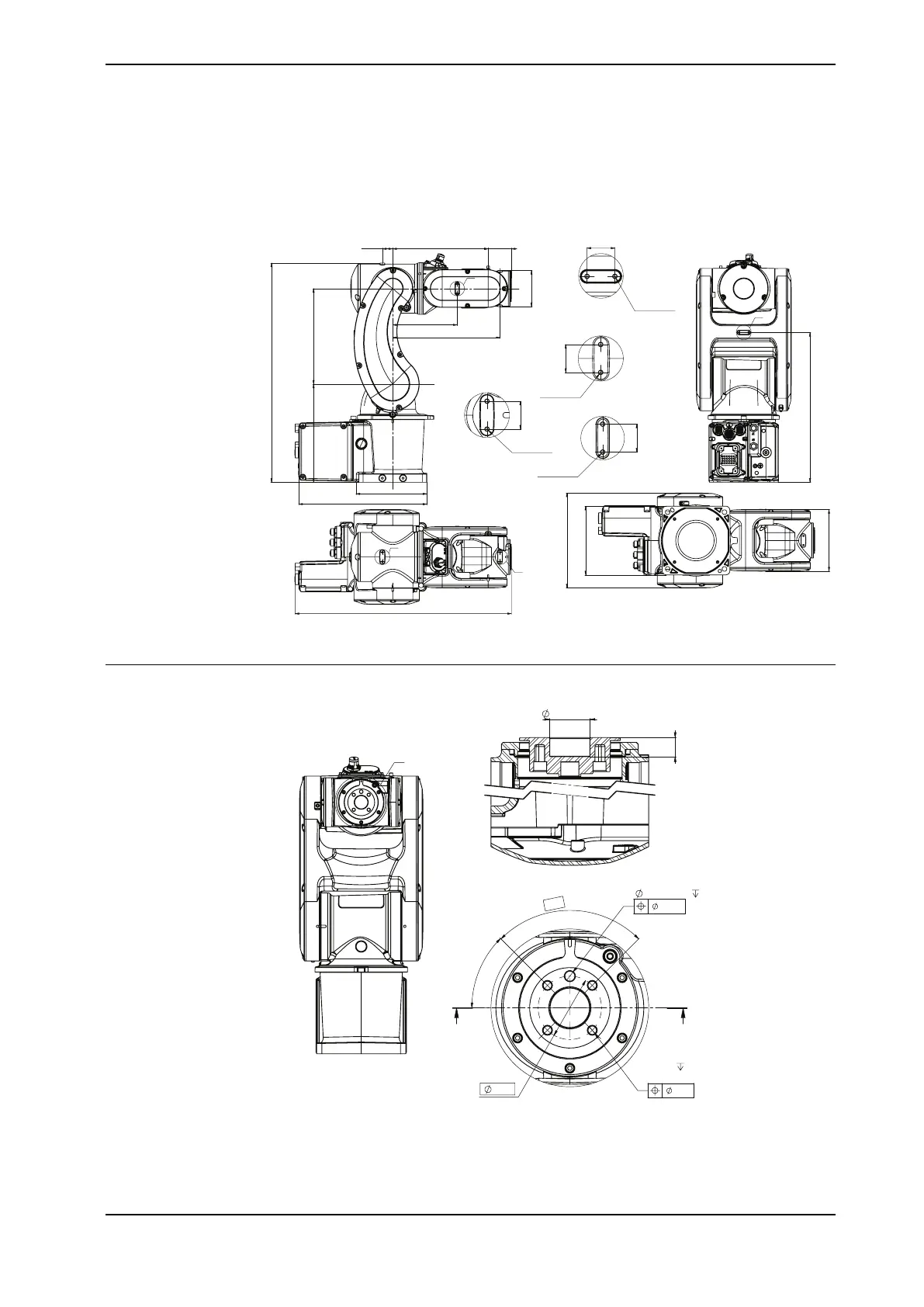
Tool flange standard
G
31,5
5 H7
+
0,012
0
7
4xM5
8
Drill dp 9.5
4x
90°
45°
I
I
DETAIL G
0.05
0.2
20 H7
+
0,021
0
9,5
I - I
xx2200000190
Continues on next page
Product manual - IRB 1010 63
3HAC081964-001 Revision: B
© Copyright 2022 ABB. All rights reserved.
3 Installation and commissioning
3.3.6 Fitting equipment on the robot (robot dimensions)
Continued