1.9 Customer connections
1.9.1 Introduction to customer connections
General
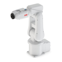
The cables are integrated in the robot and the connectors are placed on the upper
arm housing and one at the base. One connector R3.CP/CS on the upper arm
housing. Corresponding connector R1.CP/CS is located at the base. Hose for
compressed air is also integrated into the manipulator. There are 4 inlets at the
base (R 1/8”) and 4 outlets (M5) on the upper arm housing.
xx0900000264
ValueNumberDescriptionConnectionPosition
49 V, 500 mA10Customer power/signal(R1)R3.CP/CSA
Inner hose diameter 4 mm4Max. 5 barAirB
38 Product specification - IRB 120
3HAC035960-001 Revision: T
© Copyright 2010-2019 ABB. All rights reserved.
1 Description
1.9.1 Introduction to customer connections
 Loading...
