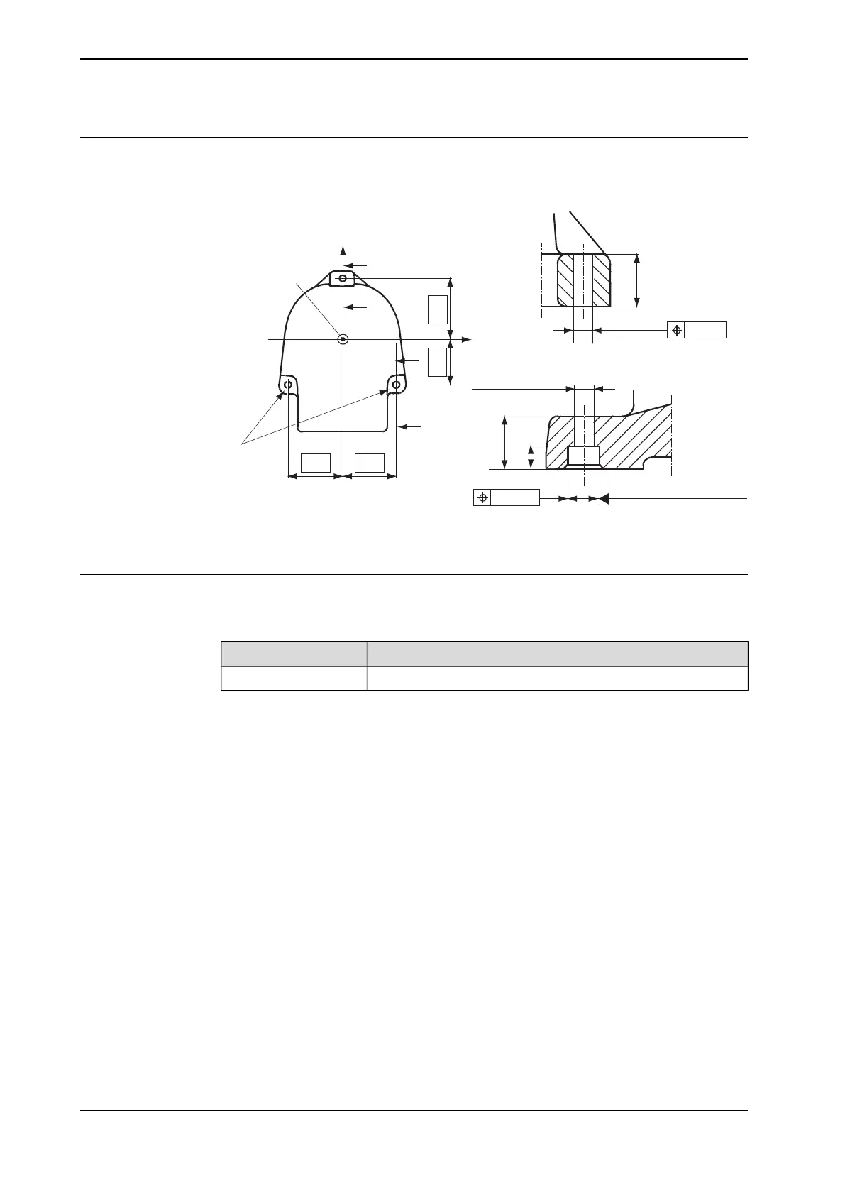
Hole configuration
The figure below shows the hole configuration of the robot base, and cross section
of the guide sleeve holes used when securing the robot.
210
280
B
A
A
260 260
(A)
Z
B
(B)
(C
)
X
Y
48
Ø 0.5
D = 18.5
B - B
D = 18.5 (2x)
48
20
Ø 0.25
D = 35 H8 (2x)
+0
.039
-0
A - A
xx1400002065
Guide sleeves
Two guide sleeves can be fitted to the two rear bolt holes to allow the same robot
to be remounted without re-adjusting the program.
Art. no.Equipment
2151 0024-169Guide sleeves
62 Product manual - IRB 2400
3HAC022031-001 Revision: P
© Copyright 2004-2018 ABB. All rights reserved.
2 Installation and commissioning
2.3.3 Orienting and securing the robot
Continued

 Loading...


