Installation and CommissioningCustomer connections on manipulator
Product Manual IRB 640 21
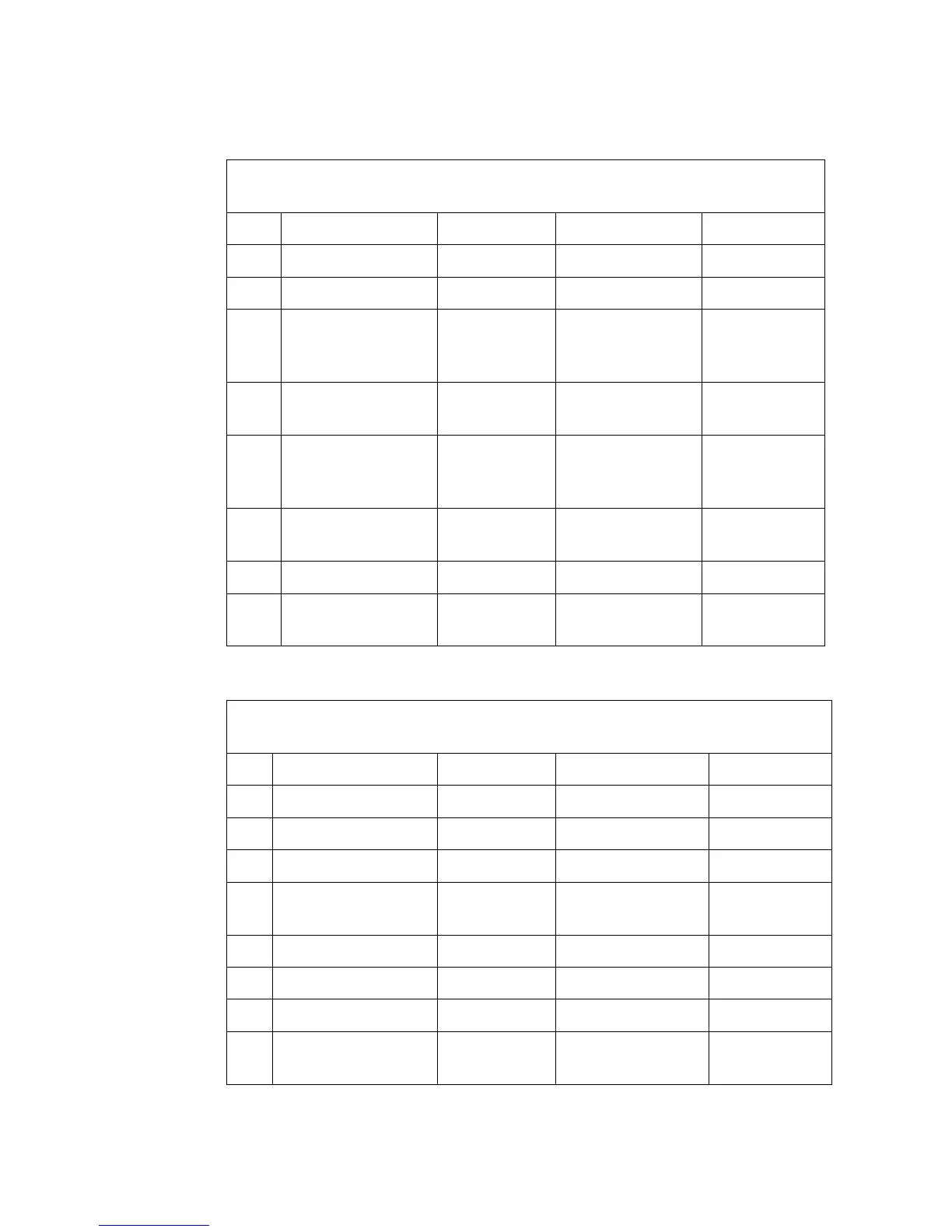
Connector R3.CP. Power signals on the upper arm. (Regarding Item No. see Fig-
ure 15)
Item Name ABB art. no. Type Comments
1 Socket con. 12p 3HAA 2613-2 UTO 014 12 SHT Burndy
2 Gasket 5217 649-64 UTFD 13 B Burndy
3 Socket See Pin and
Socket table
below
4 Pin con. 12p 3HAA 2602-2
5217 649-7
UTO 61412 PN04
UTO 61412 PN
Burndy EMC
Burndy
5 Pin See Pin and
Socket table
below
6 Adaptor 3HAA 2601-2
5217 1038-3
UTG 14 ADT
UTG 14 AD
Burndy EMC
Burndy
7 Cable clamp 5217 649-8 UTG 14 PG Burndy
8 Shrinking hose
Shrinking hose
3HAA 2614-2
5217 1032-4
Bottled shaped
Angled
Connector R1.CPV. Power signals on the manipulator base.
(Regarding Pos see Figure 15)
Pos Name ABB art. no. Type Comments
1 Pin connector 12p 3HAA 2599-2 UTO 614 12 PN04 Burndy
2 Gasket 5217 649-64 UTFD 13 B Burndy
3 Pin See below
4 Socket con. 12p 3HAA 2600-2
5217 649-53
UTO 614 12S 04T
UTG 614 12 SN
Burndy EMC
Burndy
5 Sockets See below
6 Adaptor 3HAA 2601-2 UTG 14 ADT Burndy EMC
7 Cable clamp 5217 649-8 UTG 14 PG Burndy
8 Shrinking hose
Shrinking hose
3HAA 2614-2
5217 1032-4
Bottled shaped
Angled