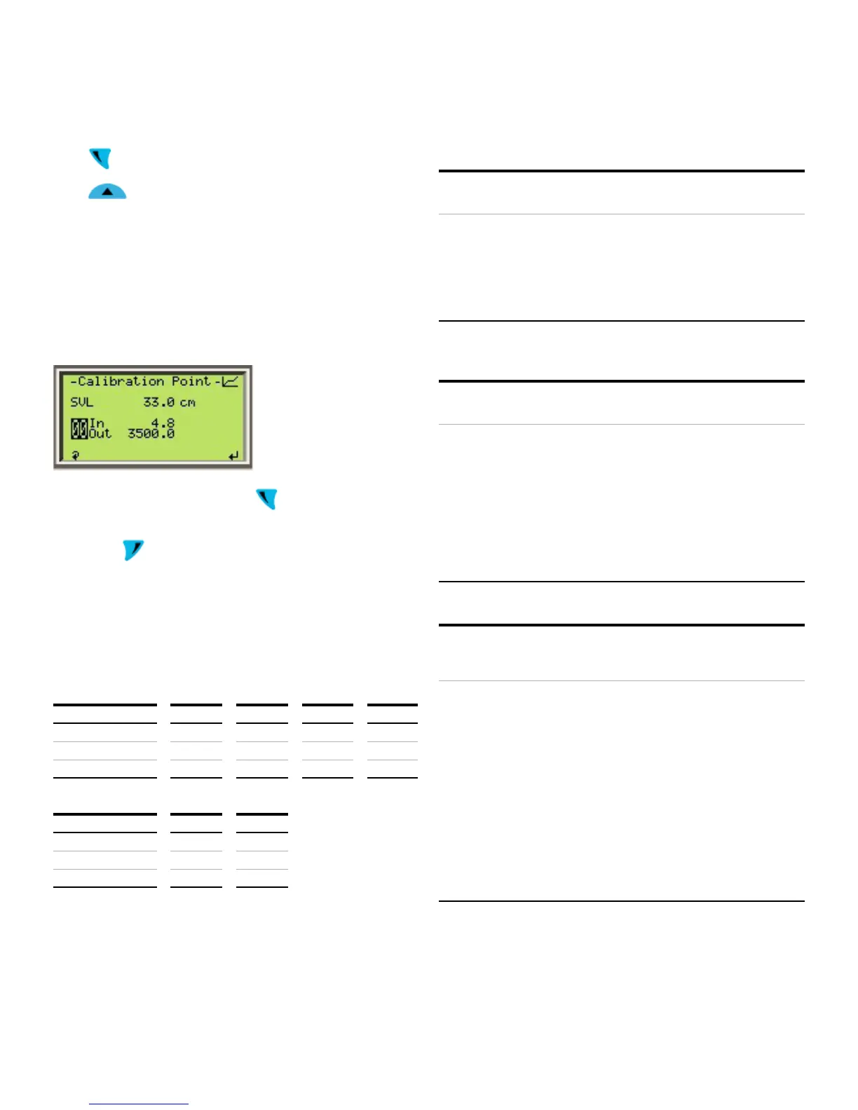
STEP 8:
Press
to scroll to the point selection
Press
to change to point 01
Repeat the operations in steps 5-7 to set the Input and Output
Values for point 01
Repeat the preceding steps for any of the 2 points if additional
fine adjustment is needed
IMPORTANT (NOTE)
The order in which the points are set is irrelevant
To exit the calibration menu, press to scroll until the point
selection is highlighted
Then, press
to go back to the previous menu
Calibration examples
1 Use of validation rule for Level Calibration
In the examples below, the Input span is 100 – 0 = 100 cm. As
such, the Output span must be between 95 and 105 cm (‘Out’
values range must be within 5% of the ‘In’ values range).
Examples of acceptable calibration:
Top Mount Case 1 Case 2 Case 3 Case 4
Point In Out Out Out Out
Examples of rejected calibration:
Bottom Mount Case 4 Case 5
Point In LVL LVL
2 Calibration moving float to both 0 and 100% points (wet
calibration)
Requirements
• Mount Orientation = Bottom or Top
Procedure
• Capture sensor value (SVL) to assign it to <In> of
• End
3 Calibration moving float only to 0% point only (partially wet
calibration)
Conditions
• Mount Orientation = Bottom or Top
Procedure
• Capture sensor value (SVL) assign it to <In> of point
(for top mounted transmitters)
• End
4 Calibration stretching the zero beyond trim points
Conditions
• Mount Orientation = Top
Procedure • Determine the lower point to measure
• Place the float in that position and inspect the
signal on the waveform screen to make sure that
there is enough signal amplitude, that is not
merging with the end of the probe
• Back off from that position until the signal is not
merging with the end of the probe and the
amplitude is the same as in the beginning of the
probe
• Measure the distance from the desired zero mark
• Set the measured distance for parameter <Out> of
• End