EasyManua.ls Logo

ABB PGC5000 Series - User Manual

ABB PGC5000 Series
88 pages
Print Icon
To Next Page IconTo Next Page
Loading...
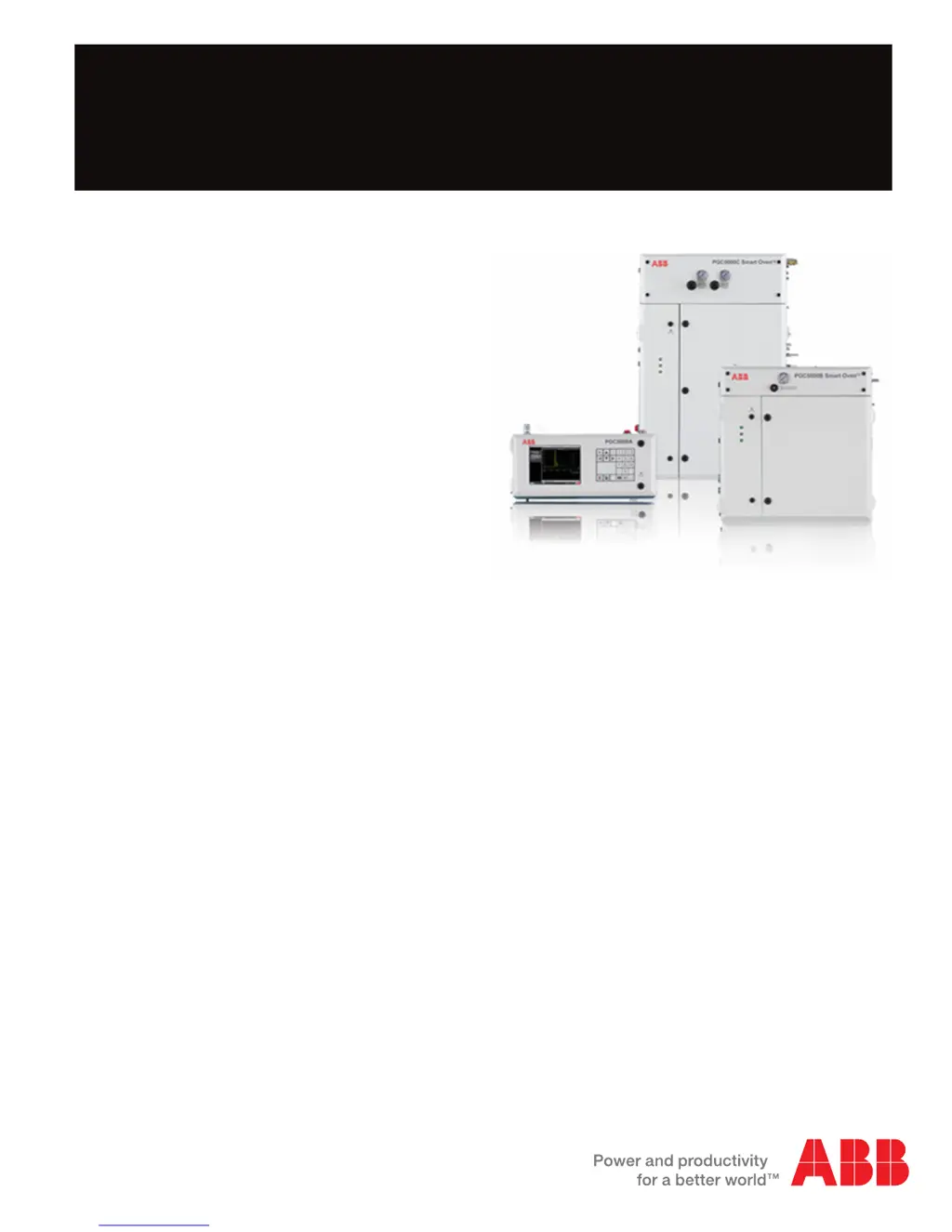
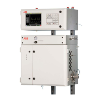
PGC5000 Series
Process Gas Chromatographs
Service Instructions SI/PGC5000-EN Rev. B
Measurement made easy

Table of Contents

Questions and Answers

  • U
    urobinsonSep 2, 2025
    How do I resolve the issue of two devices having the same CAN node ID in ABB PGC5000?
    • G
      Gregory NicholsonSep 2, 2025
      If two devices have the same CAN node ID in your ABB Laboratory Equipment, correct this by changing the node ID of one of the duplicate boards.
  • S
    Spencer HernandezSep 2, 2025
    How do I resolve a detector amplifier fault in ABB PGC5000?
    • A
      Anthony MillerSep 2, 2025
      If there is a detector amplifier fault in your ABB Laboratory Equipment, replace the amplifier assembly.
  • J
    James OsborneSep 1, 2025
    What to do if DTC did not detect AC or power to heater failed in ABB PGC5000?
    • T
      Terrance VazquezSep 1, 2025
      If the DTC did not detect AC or power to the heater failed in your ABB Laboratory Equipment, check the AC connections to the DTC assembly. Also, T-Rating faults can cause this symptom.
  • C
    Christopher JohnsonAug 31, 2025
    What should I do if the valve failed startup test on my ABB PGC5000?
    • M
      Margaret BradshawAug 31, 2025
      If the valve fails the startup test on your ABB Laboratory Equipment, check the solenoid block cable. If the problem persists, replace the faulty solenoid.
  • J
    Joyce TownsendAug 30, 2025
    What to do if the air or carrier pressure switch is open in ABB Laboratory Equipment?
    • C
      Charles DelgadoAug 30, 2025
      If the air or carrier pressure switch is open on your ABB Laboratory Equipment, verify proper air or carrier pressure and increase it if necessary. If the pressure is correct, consider replacing the switch.
  • R
    Russell SalazarAug 29, 2025
    How do I troubleshoot a temperature out of range (low) issue in ABB Laboratory Equipment?
    • K
      Kaylee NielsenAug 29, 2025
      If the temperature is out of range (low) on your ABB Laboratory Equipment, check the setting at Setup Tab>Oven>DTC# Button and adjust as needed.
  • F
    fisheralbertAug 28, 2025
    How do I troubleshoot a temperature out of range (high) issue in ABB Laboratory Equipment?
    • C
      Cindy PerkinsAug 28, 2025
      If the temperature is out of range (high) on your ABB Laboratory Equipment, check the setting at Setup Tab>Oven>DTC# Button and adjust as needed.
  • B
    brownkentAug 27, 2025
    How to fix low oven purge air pressure and open alarm on ABB PGC5000?
    • N
      Nancy WilliamsAug 27, 2025
      If you have low oven purge air pressure with an open alarm in your ABB Laboratory Equipment, check the purge pressure settings at the oven’s front panel gauge and adjust as necessary. Also, check the instrument air supply pressure and the oven gauge pressure switch.
  • M
    Michael GarciaAug 26, 2025
    What to do if ABB PGC5000 device did not communicate with Oven Controller or go online?
    • S
      Sara LunaAug 27, 2025
      If your ABB Laboratory Equipment device does not communicate with the Oven Controller or go online, check the board LEDs for any error indications.
  • S
    Sandra BlanchardAug 25, 2025
    What should I do if my ABB PGC5000 Laboratory Equipment device stopped communicating?
    • T
      tiffany79Aug 26, 2025
      If your ABB Laboratory Equipment device stops communicating, check the board LEDs for any error indications and inspect the CANbus.

Summary

Safety and symbols

Diagnostics and troubleshooting

Power

Troubleshooting power-related issues with the Master Controller and ovens.

Indicator troubleshooting procedures

Steps for identifying and troubleshooting issues based on status indicators.

Operation troubleshooting

Categorized troubleshooting for operational issues like baseline noise and offsets.

Baseline noise

Troubleshooting causes and symptoms of baseline noise in the detector signal.

Baseline or signal offset

Identifying and correcting baseline offsets due to incorrect temperatures or gas issues.

No peaks

Troubleshooting scenarios where no peaks are detected in the analysis.

Flame out led on (flame will not ignite)

Troubleshooting the flame out LED and ignition failures.

Software

Procedures for software repair and system recovery using USB flash drives.

System backup, restore and recovery

Options for creating restore points and managing chromatogram data files.

Plasma will not light

Diagnosing and resolving issues where the DID plasma fails to ignite.

No signal

Troubleshooting low or no signal output from the DID detector.

Low signal

Identifying causes for low signal output from the DID, such as restrictors or bias voltage.

Noisy

Troubleshooting causes of noisy signals in the DID detector, including connections and leaks.

High baseline

Diagnosing and resolving high baseline issues in HID mode, related to gas quality or leaks.

Drifting baseline

Troubleshooting causes of baseline drift, including pressure control and column bleed.

Spikes

Identifying causes of signal spikes, such as loose connections or unstable bias voltage.

Component repair

Replacing the EPC control pcb

Procedure for replacing the EPC Control PCB in Class B and Class C ovens.

Removing a sensor pcb

Procedure for removing a sensor PCB from the EPC control assembly.

Installing a new sensor pcb

Procedure for installing a new sensor PCB into the EPC control assembly.

Removing a proportional valve

Procedure for removing a proportional valve from the EPC control assembly.

Installing a new proportional valve

Procedure for installing a new proportional valve into the EPC control assembly.

Removing the control pcb

Procedure for removing the control PCB from the EPC enclosure.

Installing a new control pcb

Procedure for installing a new control PCB into the EPC enclosure.

Removing the heater

Procedure for removing the heater from the EPC control assembly.

Installing a new heater

Procedure for installing a new heater into the EPC control assembly.

Flame ionization detector amplifier assembly

Instructions for removing and replacing the FID Amplifier Assembly.

Flame photometric detector electrometer

Instructions for removing and replacing the FPD Electrometer.

Thermal conductivity detector amplifier assembly

Instructions for removing and replacing the TCD Amplifier Assembly.

Replacing the dtc analog pcb, version 1

Procedure for replacing the DTC Analog PCB (version 1).

Replacing the digital pcb, version 1

Procedure for replacing the DTC Digital PCB (version 1).

Replacing the dtc master analog board, version 2

Procedure for replacing the DTC Master Analog board (version 2).

Replacing the dtc digital pcb, version 2

Procedure for replacing the DTC Digital PCB (version 2).

Subassembly repair

Column repair

Procedures for removing, installing, and cutting columns.

Repairing the flame ionization detector

Instructions for repairing components of the Flame Ionization Detector (FID).

Replacing the thermocouple assembly

Procedure for replacing the thermocouple assembly in the FID detector.

Replacing the polarizer

Procedure for replacing the polarizer assembly in the FID detector.

Replacing the igniter assembly

Procedure for replacing the igniter assembly in the FID detector.

Repairing the single port thermal conductivity detector

Instructions for repairing the Single Port Thermal Conductivity Detector (TCD).

Installing the filaments

Procedure for installing new filaments in the single port TCD.

Repairing the multiport thermal conductivity detector

Instructions for repairing the Multiport Thermal Conductivity Detector (TCD).

Removing the filaments

Procedure for removing filaments from the multiport TCD.

Installing new filaments

Procedure for installing new filaments in the multiport TCD.

Repairing the flame photometric detector

Instructions for repairing components of the Flame Photometric Detector (FPD).

Replacing the photomultiplier assembly

Procedure for replacing the photomultiplier assembly in the FPD.

Replacing the burner block

Procedure for removing and installing the burner block in the FPD.

Liquid sample valve repair

Instructions for repairing the Liquid Sample Valve (LSV).

LSV disassembly on the analyzer

Step-by-step guide for disassembling the LSV on the analyzer.

CP valve repair

Instructions for repairing CP valves, including slider, wedges, and O-rings.

Replacing diaphragm valves

Instructions for replacing diaphragm valves, including four and one screw types.

Optional discharge ionization detector

Instructions for replacing components of the Optional Discharge Ionization Detector (DID).

Replacement parts

Class b main interior, both versions

List of common interior components for both Class B oven versions.

ABB PGC5000 Series Specifications

General IconGeneral
Analyzer PlatformPGC5000
TechnologyGas Chromatography
Hazardous AreaATEX, IECEx
CommunicationModbus
Measurement PrincipleGas Chromatography
Response Time30 seconds
Output Signal4-20 mA
Power Supply24 VDC or 100-240 VAC
Operating Temperature-20°C to +55°C
Enclosure RatingIP66

Related product manuals