PGC5007
PGC5007 Operating Instructions 6 Liquid sample valve repair
31 OI/PGC5007-EN, Rev C
6.2 LSV disassembly on the analyzer
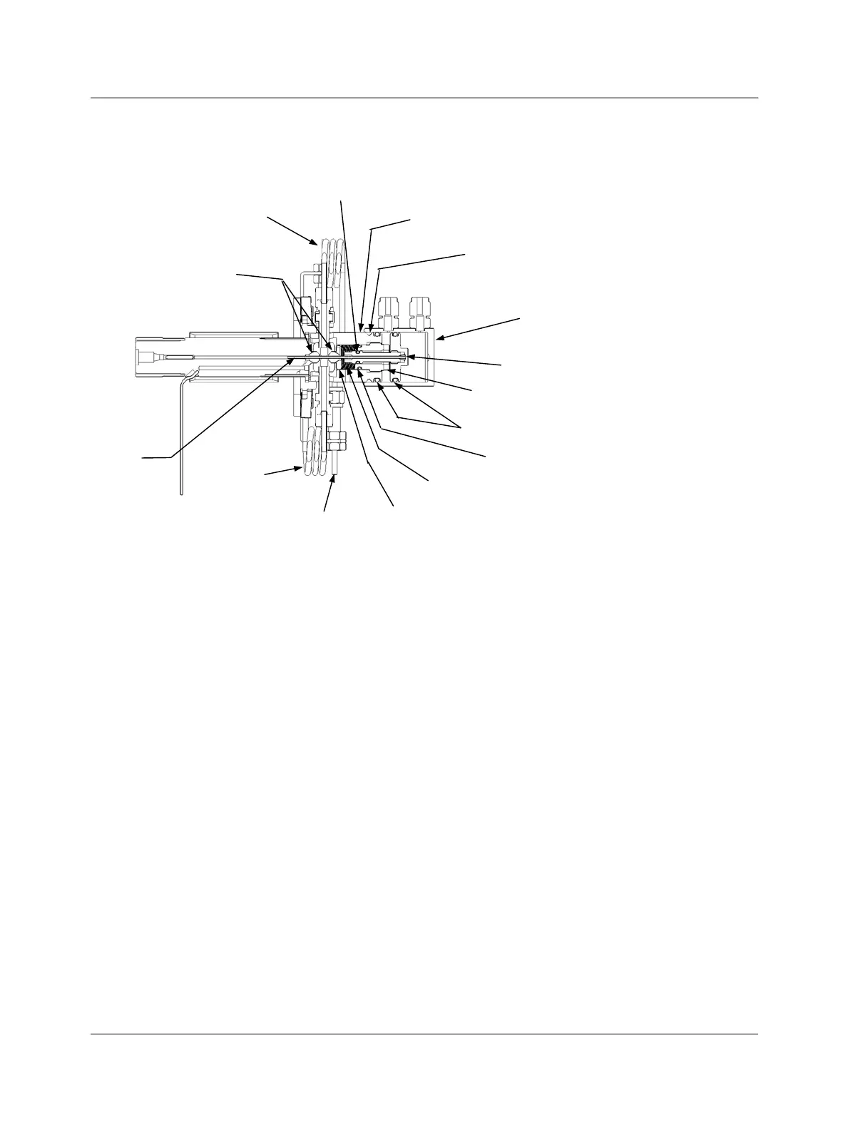
See Figure 6.2 for typical sample valve component location.
Cylinder
Piston
Tensioning Nut
Body O-Rings
Tensioning Nut
O-Ring
Cone Point Set
Screws (2)
Body
Tubing
Coils
Piston Rod
O-Ring
Rear
Valve Seat
Belleville
Springs
Tubing
Coils
Stem Seals (2)
Sample
Chamber
Stem
Fig. 6.2. Liquid Sample Valve Component Location
1. Stop the analysis at the end of a cycle.
2. Remove power from the analyzer.
3. Allow all temperature zones to cool, maintaining flow while the columns are cooling.
4. Turn off carrier, sample and air to the analyzer.
5. Open the isothermal oven door.
6. Verify that the bolt keeping the vaporizer from turning is tightened to 25 in-lb.
7. Disconnect the tubing coils from the Liquid Sample Valve.
8. Remove the two cone point set screws from the cylinder.
9. Slide the cylinder off the piston and body.
10. Using a hex key wrench, rotate the tensioning nut counterclockwise until the assembly is loose.
11. Unscrew the body from the flange and vaporizer chamber.
12. Withdraw the piston and the piston rod from the tensioning nut.
13. This will free the seals from the stem.
14. Replace the seals.
15. Inspect the stem for visible imperfections. If imperfections are found, replace the stem.
16. Remove the rear valve seat from the body.
17. Remove the 15 Belleville springs from the body.
18. Inspect the body O-rings for visible imperfections. If imperfections are found, remove the body O-rings from the body and
piston.
19. Unscrew the piston rod from the piston and extract the stem assembly from the piston rod.
20. Inspect the piston rod O-ring for visible imperfections. If imperfections are found, remove the piston rod O-ring from the
piston rod.
21. Unscrew the tensioning nut from the body.
22. Inspect the tensioning nut O-ring for visible imperfections. If imperfections are found, remove the O-ring from the
tensioning nut.